
How to Take Anchor Loads Off the Windlass Without Losing Shock Absorption
Explains why nylon diameter and deployed length must be chosen together, with steps for chain slack, chafe protection and a loose backup.
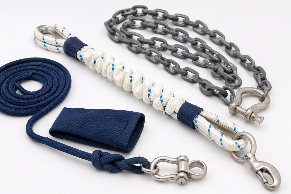
An anchor snubber has two related but distinct jobs:
- Transfer the normal anchoring load from the windlass to a properly supported deck strong point.
- Add controlled elasticity so the boat is not brought up as abruptly when the anchor chain becomes taut.
A short strop can accomplish the first job while contributing little to the second. Conversely, a long, stretchy rope is not a sound solution if its connector does not fit the chain, its lead causes chafe, or the cleat beneath it lacks suitable fasteners and backing.
That is why there is no defensible one-size-fits-all answer to “How thick and long should my anchor snubber be?” The useful answer starts with the complete load path, then balances nylon diameter and deployed length against the boat, anticipated conditions, bow geometry, swing room and practical handling.
What an anchor snubber does in an all-chain anchoring system
An anchor snubber is an elastic line connected between the anchor chain and a properly supported cleat, Samson post or other suitable deck strong point. Once deployed, it should carry the normal anchoring load instead of the windlass.
The intended load path is straightforward:
Anchor and chain → chain connector → nylon snubber → deck strong point → fasteners and backing structure
Every element matters. The snubber does not make an inadequately mounted cleat stronger, and an impressive rope breaking strength says nothing by itself about the strength of the connector, splice, fasteners or deck structure.
A windlass is primarily a machine for deploying and retrieving rode. It should not normally serve as the boat’s anchoring strong point. After the anchor is set, the working load should be transferred to a suitable stopper, snubber or other arrangement permitted by the equipment manufacturer. Nylon stretch is particularly useful with an all-chain rode because it absorbs some of the shock generated by waves and surge (West Marine’s windlass guidance).
The reason elasticity matters is snatch loading. Wind, waves, current and the vessel’s own yawing or pitching can accelerate the boat. If that movement pulls a relatively inelastic chain taut, the boat decelerates abruptly. The resulting peak load passes through the anchor, chain, connector and deck hardware.
Nylon moderates the event by extending under load. Instead of stopping the boat over a very short distance, it spreads the deceleration over a longer distance and time. This does not remove the load; it changes how abruptly the load is applied.
This distinction explains why two apparently conflicting snubber recommendations may both be reasonable:
- A short strop can transfer static and sustained load away from the windlass.
- A longer working length can provide substantially more extension and energy absorption.
Calling both items “snubbers” can hide the fact that they are optimized for different objectives.
The strongest case for a separate elastic snubber concerns an all-chain rode. A mixed rode with a meaningful working length of nylon may already provide useful elasticity. Whether it also needs a separate snubber depends on how much nylon is deployed, where the load is secured and whether the windlass is isolated from the working load.
Snubber, bridle or chain stopper: three different load-control choices
A single snubber, a two-leg bridle and a chain stopper can all take load away from a windlass, but they do not behave in the same way.
| Arrangement | Primary advantage | Main limitation |
|---|---|---|
| Single nylon snubber | Simple to rig, inspect and retrieve | Uses one primary rope and one working deck attachment |
| Two-leg nylon bridle | Uses two bow attachment points and can maintain a more central pull | Legs may not share the load equally |
| Chain stopper | Mechanically restrains chain | Adds no meaningful rope elasticity |
| Snubber plus loose backup | Combines cushioning with a secondary restraint | Backup must not engage too early |
Single snubber
A single line is usually the simplest arrangement. It runs from the chain to one suitable strong point, or through a protected centerline lead to a strong point farther aft. Fewer components can make it easier to lay out, monitor and retrieve.
Its weaknesses are equally clear: one line, one chain attachment and one working deck attachment form the primary load path. A single snubber therefore benefits from an independent backup rather than relying on the windlass if the primary line or connector fails.
Two-leg bridle
A bridle divides the boat end into port and starboard legs. It can center the pull between two bow attachment points and may be adjusted to influence yaw or the vessel’s orientation to waves.
Do not assume that each leg always carries half the load. As the boat sheers, pitches or lies asymmetrically to wind and current, one leg may carry most of it. Unless vessel-specific engineering establishes otherwise, a prudent selection assumption is that each leg and each deck attachment may be exposed to the full load (Jimmy Green Marine’s snubbing guidance).
A bridle is not automatically redundant. Both legs may depend on the same chain hook, center eye, joining splice or weak section of deck structure. A failure at that shared point can defeat both legs.
Chain stopper
A chain stopper is a mechanical restraint installed in the chain path. It can transfer chain load away from the windlass, but it does not provide the controlled stretch of a nylon snubber. Guidance that recommends taking the load off a windlass distinguishes the stopper’s mechanical holding function from the elasticity added by nylon (West Marine’s windlass guidance).
The two can therefore be complementary. The nylon line can remain the normal elastic load path, while a suitably designed and installed stopper—or chain independently secured to another proper strong point—serves as backup.
That backup should remain loose enough to permit the planned snubber extension during normal operation. If it becomes taut during ordinary vessel movement, the load bypasses the nylon and the arrangement behaves more like an inelastic all-chain system. The backup also needs its own suitable load path; attaching it to weak hardware does not create meaningful redundancy.
How to choose rope material, diameter and usable length
The best-supported general-purpose rope material for an anchor snubber is nylon. Both three-strand and multiplait nylon appear in practical guidance. Neither construction should be declared universally superior without comparing the manufacturer’s data for strength, elongation, splicing, heat buildup, chafe resistance and handling.
Polyester can be used, but it is less elastic than nylon and generally needs more deployed length to provide comparable cushioning. The available evidence does not support a universal conversion ratio.
Diameter and length must be chosen together
A thicker line generally offers more ultimate strength and more material to lose through wear, but it stretches less under the same load. A smaller-diameter line generally extends more readily, but it has less ultimate strength and may have a shorter fatigue or chafe life if repeatedly worked hard.
Length changes the same equation. More usable nylon provides more potential extension and a greater distance over which to decelerate the boat. It can also reduce the percentage extension demanded from each section of rope for a given energy input.
The trade-off prevents diameter from being considered in isolation. Selecting the thickest line that fits the cleat may produce a strong assembly that barely stretches under routine loads. Selecting a thin line solely for elasticity may leave insufficient strength, fatigue margin or chafe life. Manufacturer elongation and load data are more useful than diameter alone.
What the published calculations show
One published analysis illustrates the relationship rather than establishing a sizing rule. It estimates that 30 feet of 1/2-inch nylon can absorb approximately 1,440–1,500 joules at about 900 pounds of tension. In the same calculation, increasing the rope to 60 feet absorbs the stated energy at roughly half the percentage extension. The analysis also shows why increasing diameter is not automatically better for cushioning: at the same stated tension, thicker rope stretches less (Sail Magazine’s anchor-snubber analysis).
Those figures depend on assumptions about rope behavior, vessel mass, vessel speed and loading. They explain the interaction between diameter and length; they do not establish that 1/2-inch rope is suitable for a particular boat or installation.
Why published length recommendations vary
Published recommendations span very different intended uses. One practical article describes a basic arrangement of no more than about two metres and a longer severe-condition arrangement of about six metres, while other specialist guidance discusses lengths longer than the boat and up to approximately 60 feet (Sail-World’s practical snubber guidance).
This range is less contradictory once the intended function is identified.
A short line can:
- transfer the load off the windlass;
- reduce chain noise at the roller;
- fit a compact foredeck;
- be easier to connect and recover.
A longer line can:
- provide more potential stretch;
- absorb more motion without reaching the same percentage extension;
- reduce abrupt loading in a suitable installation;
- allow deployment to be adjusted as exposure increases.
Extra length also introduces disadvantages:
- more line to deploy and retrieve;
- more chain slack to manage;
- greater risk of seabed contact or fouling;
- greater swing-room demand;
- more opportunities for chafe;
- more complicated handling at the bow.
Practical Sailor describes approximately 18–30 feet as a reasonable range for experimentation while acknowledging that little research defines an ideal length and that configurations vary by boat. Treat that range as a provisional routine-use reference, not a standard or guaranteed safe dimension (Practical Sailor’s snubber testing and guidance).
A vessel-specific selection framework
Before selecting diameter or usable length, identify:
- Loaded displacement: Use the boat’s realistic cruising weight, not an optimistic lightship figure.
- Windage: Freeboard, deckhouses, enclosures, masts and rigging influence force and motion.
- Chain dimensions: The connector must fit the actual chain links.
- Expected conditions: Separate protected daytime use from overnight, exposed and heavy-weather planning.
- Yaw and surge: A boat that sails widely at anchor may generate higher peaks than one that lies quietly.
- Bow geometry: Rollers, sprits, chocks and stem fittings control the available lead.
- Strong-point location: A longer on-deck run may add usable rope but also introduces more chafe sites.
- Swing room: More rode and snubber deployment enlarge the boat’s practical footprint.
- Seabed clearance: A long snubber that drags can abrade or foul.
- Handling: Crew must be able to deploy, monitor and retrieve the arrangement without entering dangerous bights or handling heavily loaded gear.
There is no well-supported universal boat-length-to-rope-diameter table, nor one ideal deployment length. Confirm the rope’s rated properties and compatibility with the connector, chain and deck hardware. For heavy-weather loads, unusual geometry or uncertain deck structure, obtain advice from the relevant manufacturers or a qualified marine professional.
Choosing the chain connector and protecting the complete load path
The chain connector must stay attached during normal cycling, fit the actual chain and remain practical to deploy and retrieve at the bow.
Open versus captive hooks
An open or non-captive hook is straightforward to place on compatible chain. Its weakness appears when the line goes slack: without tension keeping it seated, it may release. Deployment therefore requires positive control of the line while chain is paid out.
A captive or retentive hook is designed to remain attached more reliably during slack moments. That can improve retention, but the locking feature may make the connector harder to fit or remove around a crowded bow roller. Some designs may also be awkward to release under load. Retailer guidance describing both types emphasizes this retention-versus-handling trade-off rather than identifying one universal winner (Jimmy Green Marine’s chain-snubber guide).
Other documented attachment choices include:
- correctly sized grab hooks;
- Dyneema soft shackles;
- rope hitches;
- Prusik-style attachments;
- loops and slings.
These options have different trade-offs in retention, chafe, chain contact, release and inspection. The available evidence does not justify ranking one as universally safest.
Fit the chain you have, not merely its label
Nominal chain size is not enough to establish compatibility. Link dimensions and specifications can vary. Confirm the connector against the actual chain dimensions, using current manufacturer fit information and, where practical, a physical check before relying on it.
A connector should seat in its intended manner without being forced, rocking into an unintended position or bearing on an edge not designed for the load. It must also be deployable around the actual bow roller and stem arrangement.
Do not improvise connector compatibility at anchor. If fit, load direction or release behavior is uncertain, resolve it before the equipment is needed.
Thimbles, shackles and splices
Where the assembly uses them:
- A thimble supports a rope eye and limits tight bending or direct metal-on-fiber wear.
- A shackle joins compatible eyes or fittings and must suit the expected loading direction.
- A splice should be appropriate to the rope construction, properly formed and regularly inspected.
Additional hardware can improve geometry or serviceability, but every fitting adds another compatibility, corrosion and inspection point. Follow the rope and hardware manufacturers’ instructions rather than relying on generic assumptions about retained strength.
Audit the entire load path
Evaluate:
- Nylon rope
- Splice or knot
- Thimble
- Shackle, hook or soft connector
- Anchor chain
- Cleat, bitt or Samson post
- Fasteners
- Backing plate and underlying structure
Rope strength alone cannot establish a safe working load for this assembly. A complete rating would have to account for every component, its installation, load direction, age and condition. The available sources do not provide verified working loads for complete vessel installations.
Use this checklist when comparing connectors:
| Question | What to verify |
|---|---|
| Does it fit? | Actual chain-link dimensions and intended seating |
| Does it remain attached when slack? | Retention mechanism or controlled deployment method |
| Can it be handled safely? | Access forward of the roller and the retrieval procedure |
| Is it appropriately rated? | Current manufacturer load information and limitations |
| Can it tolerate the environment? | Material compatibility, wear and corrosion condition |
| What can rub? | Rope, chain, hook, thimble and adjacent bow hardware |
| Can it be inspected? | Visibility of wear, deformation and splice condition |
Commercial listings illustrate the available forms rather than proving suitability. The supplied seller material includes single lines, bridles, catamaran snubbers and separate hooks in several listed lengths and diameters. Such listings are not independent performance evidence and do not establish that a product fits a particular vessel or chain (dbRopes’ anchor-snubber collection). Recheck specifications, ratings, price and availability directly with the seller or manufacturer on the date of publication or purchase.
How to deploy an anchor snubber step by step
Deploy the snubber after the anchor has been set and the set has been checked. A snubber cannot correct an anchor that has not dug in, insufficient scope or unsuitable holding ground.
The exact handling sequence depends on whether the assembly has a fixed-length eye or bridle, or an adjustable boat end. In a common fixed-length arrangement, the boat end is secured or positively controlled, the chain attachment is made, and chain is paid out until the intended length lies beyond the bow. With an adjustable arrangement, the crew may control or ease the boat end to establish the working length. In either case, keep the line controlled and follow the connector and windlass manufacturers’ procedures.
-
Set and verify the anchor. Complete the normal setting procedure and check the boat’s position and behavior. Continue monitoring for drift.
-
Prepare the snubber on deck. Flake or lay out the line so it can run without knots or tangles. Inspect the connector, splice and chafe gear. Keep hands, feet and loose clothing out of bights.
-
Secure or positively control the boat end. For a fixed-length line or bridle, make the boat end fast to its intended strong point when appropriate for the connector and layout. For an adjustable line, lead it fairly and maintain positive control through the approved securing arrangement. Securing the boat end before using a non-captive hook also reduces the chance of losing the complete assembly.
-
Attach to the chain forward of the windlass. Fit the hook, soft shackle or rope attachment to the chain. If the connector cannot pass safely through the bow roller, attach it forward of the roller or guide it around the roller according to the hardware’s intended procedure.
-
Maintain tension on a non-captive hook. Keep the line controlled while paying out chain. A slack moment before an open hook is loaded can allow it to fall free.
-
Establish the intended working length. With a fixed-length arrangement, pay out chain while keeping the snubber controlled until the intended length is deployed. With an adjustable boat end, ease only as the approved deck arrangement permits. Do not stand in the line’s potential recoil path.
-
Position the lead and chafe protection. Cover every likely contact zone, including rollers, chocks, fairleads, stem fittings and deck edges. Confirm that pitching and yaw will not move the rope beyond the protected area.
-
Make the line fast if it is not already secured. Use the intended cleat, bitt or Samson post and an appropriate securing method. For a bridle, route both legs fairly and secure them to their respective strong points.
-
Ease more chain until the nylon takes the load. Continue paying out chain until a visible slack loop hangs between the connector and windlass. The snubber—not the windlass—should now carry the working load.
-
Provide sufficient chain slack. The loop must accommodate the expected snubber extension and normal vessel motion. If it straightens before the nylon has delivered useful stretch, the chain bypasses the cushioning effect.
-
Set the independent backup. Engage a suitable stopper or independently secure the chain, but leave enough slack that it does not become the normal load path.
-
Verify the complete arrangement. Confirm that the windlass is unloaded, the connector remains seated, the line has a fair lead, chafe gear stays in place and neither rope nor hardware is contacting a damaging surface or the seabed.
Specialist deployment guidance follows this broad sequence: set the anchor first, connect forward of the windlass, control the line during payout, protect the leads, add chain slack and verify that the windlass is unloaded (Snubberhead’s deployment guide).
A useful onboard diagram should show:
                     LOADED NYLON SNUBBER
Deck strong point ===========================\
[backed cleat/post] [chain connector]
                                                  X================ anchor chain
Loose backup  - - - - - - - - - - - - - - - - /                   to anchor
\
Windlass [UNLOADED] ---- slack chain loop ------------\

Mark chafe protection at every roller, chock, fairlead,
stem fitting or deck edge touched by the loaded nylon.
The sketch is conceptual. Actual leads, connector orientation and strong points must follow the boat and equipment manufacturers’ instructions.
Chafe, slack and geometry: the setup details that determine whether it works
A theoretically well-sized rope can fail early—or stop cushioning effectively—because of its lead, inadequate chain slack or changing vessel geometry.
Map every potential chafe point
Inspect the line’s path at rest and while the boat yaws or pitches. Likely contact points include:
- bow roller cheeks and axle areas;
- chocks and fairleads;
- stem fittings and anchor platforms;
- pulpit bases or nearby fittings;
- deck and toe-rail edges;
- cleat horns and bases;
- rough surfaces beneath a loaded turn;
- the chain or connector itself.
Fit appropriate anti-chafe protection at every likely friction point. The protection must remain over the contact area throughout expected movement. A sleeve that migrates aft while the rope saws across a forward edge offers little protection.
Chafe gear also requires inspection. Grit trapped inside a sleeve, a hardened edge or movement between the sleeve and rope can create wear that is not immediately visible. Practical testing and guidance consistently treat fair leads, chafe protection and keeping the line clear of the seabed as essential parts of the installation rather than optional accessories (Practical Sailor’s snubber testing and guidance).
Too little chain slack bypasses the snubber
A slack chain loop is functional reserve, not decoration. As nylon extends and the bow moves, the loop shortens. If the chain becomes taut first, the inelastic chain carries the peak while the remaining potential stretch in the rope is bypassed.
There is no universal slack distance or percentage. The required amount depends on deployed nylon length, expected extension, bow height, waves, pitching and changing vessel orientation.
Observe the loop after deployment and recheck it when conditions change. If adjustment is needed, follow the equipment procedures and make the change only when it can be done safely. Do not approach, release or reposition heavily loaded rope or chain in energetic conditions merely to improve the appearance of the loop. Deployment guidance treats slack as something that must exceed expected extension, but any starting estimate still requires vessel-specific judgment (Snubberhead’s deployment guide).
Too much deployed length creates new problems
More nylon is not always better. Excess length may:
- touch or drag on the seabed;
- foul the anchor, chain or underwater appendages;
- complicate retrieval;
- require more room than the anchorage permits;
- introduce new chafe points;
- make rapid adjustment more difficult.
Keep the snubber clear of the bottom where practical. Choose the longest useful deployment that the geometry and anchorage can support, rather than automatically deploying the longest line carried aboard.
Yaw changes both load and lead
A boat that sails from side to side at anchor gains speed before being checked by its rode. That motion can create substantial peak loading and move the working rope across rollers, chocks and fittings.
A bridle may alter the vessel’s behavior, but its geometry changes continuously as the boat swings. One leg may unload while the other carries most of the force. Wider included angles also alter the forces in the legs and their attachments; generic guidance cannot quantify those loads for a particular boat.
Adjusting bridle-leg length may improve orientation in some combinations of wind, current and swell. It can also create uneven loading or an unfair lead. Treat motion control as a conservative, boat-specific adjustment—not proof that the load is evenly distributed.
Troubleshooting table
| Symptom | Possible issue | What to check |
|---|---|---|
| Chain rattles on the roller | Snubber may not be carrying the load, or the lead may be poor | Confirm the rope carries the working load and the chain has a visible loop |
| Slack loop repeatedly becomes taut | Chain slack may be insufficient, or motion may exceed the planned deployment | Reassess slack and working length when conditions permit safe adjustment |
| Open hook repeatedly releases | Hook may lose tension, fit poorly or sit at an unfavorable angle | Verify chain compatibility and controlled payout; consult the connector manufacturer |
| One bridle leg remains slack | Vessel alignment or unequal geometry | Assume the loaded leg may carry most or all of the load; inspect both leads and attachments |
| Chafe sleeve moves away | Protection may be too short or improperly secured for the movement | Reposition, extend or secure it as appropriate for that layout |
| Rope appears to stretch excessively | Possible causes include high loading, unsuitable diameter, damage or material condition | Reduce exposure if possible and consult manufacturer data or a qualified inspector |
| Rope barely stretches and snatch remains harsh | Possible causes include insufficient usable length, excessive diameter or early engagement of the chain or backup | Check the entire arrangement before changing a safety-critical component |
| Snubber contacts the seabed | Excess deployment, shallow water or tidal change | Shorten or reroute only when safe while preserving useful stretch and chain slack |
| Windlass takes load intermittently | Chain loop may be disappearing or the backup may be engaging too early | Restore the intended load path when conditions permit safe handling |
These entries are diagnostic starting points, not proof of a single cause. Rope construction, age, temperature, knots, splices, vessel motion and hardware geometry can all affect behavior.
Routine anchoring, exposed conditions and backup planning
The same configuration need not serve every anchoring situation.
Calm short stops
For a short stop in settled conditions, the immediate goal may be to transfer load off the windlass with a simple, manageable arrangement. Even then, use a suitable strong point, fair lead and compatible connector.
A short strop should not be mistaken for a high-energy shock absorber. It may unload the windlass effectively while providing relatively little working stretch.
Routine overnight anchoring
Overnight use deserves enough working length for useful extension, deliberate chafe protection, adequate chain slack and an independent backup. Check the setup after the boat settles into its normal pattern and after changes in wind, current or tide.
Plan for darkness. The connector, deck attachments and backup should be identifiable and accessible without improvisation. Keep suitable lighting and retrieval equipment ready, but do not plan on handling heavily loaded gear from an exposed foredeck.
Exposed anchorages
With greater fetch, swell, gusts or strong current, vessel motion becomes more important. A longer usable snubber, a carefully configured bridle, stronger or separate gear and more deliberate redundancy may be appropriate. These choices also require adequate swing room, fair leads and seabed clearance.
Published wind thresholds and dimensions are best treated as personal or provisional guidance rather than transferable operating limits. Boats of equal length can differ sharply in displacement, windage, yaw behavior, foredeck structure and anchoring geometry.
Heavy-weather preparation
Heavy-weather planning should occur before conditions deteriorate. One approach is to carry separate everyday and heavy-weather snubbers: the routine line is selected to stretch under ordinary loads, while the heavy system is selected for higher anticipated loads and may add usable length or redundancy. This is a planning model, not a guarantee or mandatory configuration.
An independent backup can limit the immediate transfer of load to the windlass if the primary rope or connector fails. It must have a suitable load path of its own and enough slack to preserve the primary snubber’s normal extension.
A backup that is already tight can defeat that purpose by bypassing the nylon before it has done useful work. Practical heavy-weather guidance also emphasizes that longer or stronger arrangements must be selected around the individual boat rather than copied from another owner’s wind threshold or rope size (Sail Magazine’s anchor-snubber analysis).
No snubber replaces:
- adequate scope;
- a properly selected and set anchor;
- suitable chain and connectors;
- sound, properly backed deck hardware;
- monitoring the forecast and boat position;
- keeping a safe watch;
- leaving an anchorage that is becoming unsafe.
Follow the instructions for the boat, windlass, chain stopper, connector and deck hardware. Heavy-weather load planning or uncertain deck construction warrants help from the relevant manufacturers, a qualified rigger, naval architect or other competent marine professional.
Inspection, maintenance and retirement checklist
Inspect an anchor snubber as a system, not merely as a rope.
Before deployment
Check:
- the entire line for cuts, abrasion, stiffness, glazing and contamination;
- eye splices for movement, distortion or damaged strands;
- knots, if used, for correct formation and adequate tails;
- the chain connector for proper fit and free operation;
- hooks, shackles and thimbles for wear, deformation or corrosion;
- chafe gear for coverage and secure positioning;
- the intended rope lead for sharp edges or interference;
- cleats, bitts or posts for movement, cracking or loose fasteners;
- visible deck and backing structure around the strong point;
- chain-stopper operation and the independent backup arrangement.
If a connector has become deformed or no longer seats correctly, do not rely on it.
While loaded
Confirm that:
- the nylon carries the normal anchoring load;
- the chain between the connector and windlass remains slack;
- the hook or other connector stays properly seated;
- the windlass remains unloaded;
- both bridle leads remain fair, even if only one is heavily loaded;
- chafe protection remains over every contact point;
- the rope stays clear of the seabed and fouling hazards;
- the backup remains loose enough to preserve useful stretch.
Recheck after a wind shift, tide change, increase in waves or noticeable change in the boat’s motion. Monitoring does not require handling a loaded system; make physical adjustments only when the procedure and conditions allow them to be performed safely.
After use
Look for:
- surface fuzzing or localized abrasion;
- glazing, melting or hard shiny patches;
- stiffness or hard sections;
- frayed, cut, flattened or pulled fibers;
- discoloration or contamination;
- splice movement;
- thimble distortion;
- elongated, cracked or bent hooks and shackles;
- corrosion or binding mechanisms;
- displaced, cut or worn-through chafe sleeves;
- loosening or movement at deck hardware.
Dry the line when practical, limit unnecessary ultraviolet exposure and store it so that the connector cannot damage the rope.
Treat the snubber and its chafe gear as consumable components. There is no credible universal replacement interval because service life varies with anchoring frequency, ultraviolet exposure, wet storage, contamination, chafe and repeated high-load cycling. Specialist maintenance guidance therefore emphasizes recurring inspection for rope damage, stiffness, corrosion and fitting deformation rather than relying on appearance or age alone (Snubberhead’s snubber and bridle guidance).
After a known overload, do not assume a component is sound merely because it looks acceptable. Retire suspect rope or hardware, particularly after severe chafe, heat damage, significant connector deformation or unexplained splice movement. Where the consequence of failure is serious and condition is uncertain, obtain a qualified inspection.
Anchor snubber FAQ
Does an all-chain anchor rode need a snubber?
An all-chain rode has little rope elasticity in its normal working section, so a correctly selected and installed nylon snubber is generally advisable. It transfers the working load from the windlass to suitable deck structure and moderates abrupt deceleration when vessel motion pulls the chain taut. The complete load path—including the connector, cleat, fasteners and backing—must still be suitable for the duty.
A chain stopper can also unload the windlass, but it does not provide the same cushioning. Depending on the vessel and manufacturer instructions, the stopper and snubber may serve complementary roles.
How much slack chain should be left after deploying the snubber?
Leave enough that the chain loop remains slack throughout the snubber’s expected extension and normal vessel motion. If the loop straightens, taut chain bypasses the nylon’s remaining cushioning.
A fixed distance or percentage cannot cover every installation. Required slack changes with nylon length and diameter, bow height, waves, yaw and the geometry between the connector and windlass. Begin with a clearly visible loop and monitor it under normal movement, but adjust loaded equipment only when doing so is safe and consistent with the equipment procedures.
Is a bridle better than a single anchor snubber?
Not universally. A single snubber is simpler to rig and inspect. A bridle uses two bow attachment points, can maintain a more central pull and may help manage vessel orientation.
However, bridle legs do not necessarily split the load equally. One leg may carry most of the force as the boat swings. A bridle may also retain common failure points such as one chain connector, one center splice or inadequately supported deck structure (Snubberhead’s comparison of snubbers and bridles).
Choose according to bow geometry, vessel motion, strong points and crew handling—not on the assumption that two legs automatically provide full redundancy.
Can a chain stopper replace an anchor snubber?
A suitably designed and installed stopper can replace the snubber’s load-transfer function by keeping the normal anchoring load off the windlass. It cannot replace the useful elasticity of nylon.
For an all-chain rode, one layered arrangement uses an elastic snubber as the normal load path and a suitably installed stopper or independently secured chain as a loose backup. The backup should not become taut during normal snubber extension (Jimmy Green Marine’s anchor-snubbing guidance).
Does a mixed rope-and-chain rode still need a separate snubber?
Not always. If a meaningful working length of nylon rode is deployed and carries the load from the chain to a proper strong point, the rode may already provide useful elasticity.
A separate snubber may still be useful if the working configuration leaves the load on the windlass, the nylon section is not deployed, the bow lead needs changing or additional chafe isolation is required. Evaluate the actual loaded configuration rather than deciding solely from the fact that some rope exists in the rode.
The final decision sequence
The compact sequence to save is:
Set → connect → protect → slacken → unload → back up → monitor → inspect.
In practice:
- Identify the intended load path.
- Confirm that every strong point, fastener and connector is suitable.
- Choose nylon that can provide useful stretch at the expected loads.
- Deploy enough line for the conditions and available space.
- Preserve a chain loop that remains slack during normal extension.
- Protect every potential chafe point.
- Keep an independent, appropriately loose backup.
- Monitor without entering bights or handling heavily loaded gear.
- Inspect the complete system after use.
The final decision is not simply “buy this diameter.” Generic guidance can explain the trade-offs among strength, elasticity, length, geometry and handling. Vessel-specific load ratings and heavy-weather suitability require manufacturer documentation or qualified marine advice.