
How to Choose the Right Bow Shackle for the Load and Connection
A six-step method checks application, WLL, load direction, pin style, measured fit and environment, with side-loading and clearance cautions.
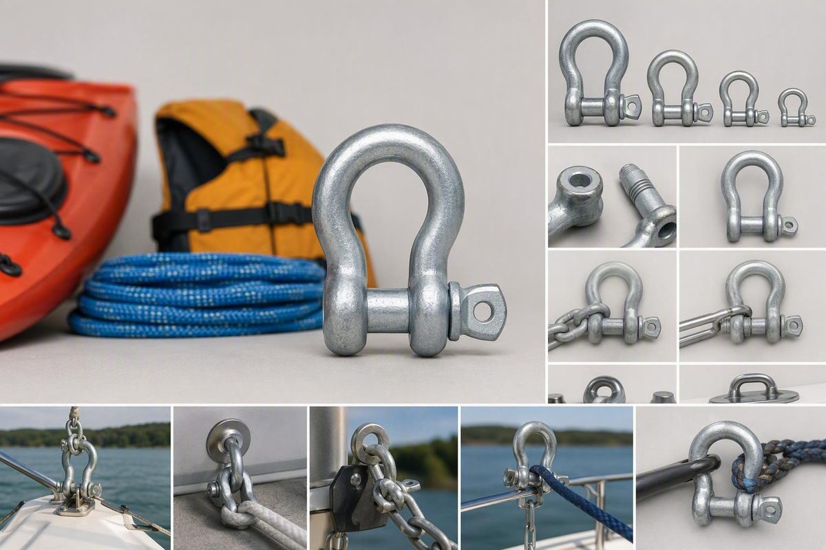
Choose an anchor shackle by checking six factors separately: the application, required working load limit (WLL), load direction, pin style, measured fit, and operating environment. An anchor shackle—also called a bow shackle—is a removable-pin connector with a broad, rounded body. That shape provides more internal clearance than a narrow D or chain shackle, but it does not authorize unrestricted side loading. Nominal diameter or corrosion-resistant material alone cannot establish suitability.
Related: Anchor Swivel: Do You Need One? Selection and Installation Guide.
The short answer: what an anchor shackle is and how to choose one
An anchor shackle has a rounded bow, two ears, and a removable closing pin. Compared with a D or chain shackle intended primarily for compact, in-line connections, its wider body can accommodate larger attachment points and changing connection geometry more easily.
Use this six-step selection sequence:
- Identify the application. Define whether the shackle will serve an anchor rode, lift, tow, mooring, or another rigging system.
- Determine the required rating. Establish the required WLL from the design basis for the complete system—not from shackle diameter alone.
- Check load direction. Identify in-line loading, side loading, racking, bending, or contact with the pin threads.
- Choose the pin style. Match the retention method to how often the connection is opened and whether it will experience movement or vibration.
- Measure every connection point. Check the chain link, anchor attachment point, pin, bow, roller, stopper, and windlass path.
- Account for the environment. Consider saltwater, immersion, coating wear, dissimilar metals, inspection access, and adjoining hardware.
The broad bow provides clearance; it is not blanket permission to pull from any angle. Approval or rating in one context is also not automatic approval for another.
Compare screw-pin, bolt-type, safety-bolt, and round-pin shackles
Pin design affects convenience, retention, and application limits. Specialist rigging guidance generally associates screw pins with temporary or frequently changed connections and bolt-type pins with longer-term or vibration-prone assemblies, but the exact product instructions control.1
| Pin style | Retention | Main selection limit |
|---|---|---|
| Screw pin | Threaded pin in the ear | Movement can loosen it; use only the approved retention arrangement |
| Bolt type | Bolt, nut and cotter pin | All specified parts must be fitted correctly |
| Safety bolt | Product-specific locking arrangement | Verify both anchor and shackle approval |
| Round pin | Unthreaded pin and specified retainer | Product-specific loading limits; G-213 prohibits side loading |
Safety-bolt shackles can be an anchor-specific alternative where both the anchor and shackle manufacturers permit them.
Safety callout: Crosby expressly states, “DO NOT SIDE LOAD ROUND PIN SHACKLES” for its G-213 model. This is a model-specific prohibition, not a rule that should be generalized or diluted. See the Crosby G-213 product instructions.
Do not improvise retention based on appearance. Use the pin supplied or specified for the shackle and follow both manufacturers’ instructions for seating, cotter pins, seizing, or any other permitted locking method.
Start with working load limit—not nominal shackle size
Working load limit is the maximum load a shackle is designed to carry under its stated normal working conditions. It is distinct from breaking strength and must be considered with the actual load direction, pin type, fit, and manufacturer instructions.2
Do not confuse WLL with:
- Proof load: a specified test load applied under defined conditions.
- Breaking strength: a failure-related value, not a normal operating limit.
- Design factor: a stated relationship between a rated load and a defined failure measure.
- Fatigue rating: performance under a specified number and magnitude of load cycles.
These values are not interchangeable.
Purchase against the exact model and current manufacturer table—not a generic description such as “5/16-inch shackle.”
Use the applicable system design basis, current instructions for the anchor, chain, shackle, windlass, and adjoining equipment, plus any professional or regulatory requirements governing the service.
Crosby’s G-213 illustrates why the terminology matters. Crosby lists a 6:1 design factor, a maximum proof load of twice WLL, and a fatigue rating of 20,000 cycles at 1.5 times WLL. These are manufacturer claims rather than independent test findings, and none permits operation above WLL or outside the model’s loading restrictions.3
Measure the complete connection before buying
Strength and fit are separate gates. First identify a shackle with the required rating and an allowable load path. Then verify that the exact product fits without forcing, binding, or downsizing.
For a common anchor-to-chain arrangement, the pin must pass through the intended chain end link, while the shackle body must fit through the anchor’s rode attachment point.
Record every measurement in one unit system:
| Measurement | Value | Unit |
|---|---|---|
| Shackle pin diameter | ______ | ______ |
| Shackle body diameter | ______ | ______ |
| Jaw opening | ______ | ______ |
| Inside width | ______ | ______ |
| Chain-link aperture: width × length | ______ | ______ |
| Anchor attachment-point thickness | ______ | ______ |
| Anchor attachment-point opening | ______ | ______ |
| Bow-roller clearance | ______ | ______ |
| Chain-stopper clearance | ______ | ______ |
| Windlass or deck-path clearance | ______ | ______ |
General marine guidance suggests starting with a shackle one nominal size larger than the chain. West Marine, for example, pairs 1/4-inch chain with a 5/16-inch shackle. This is only a starting point: the WLL, pin diameter, body diameter, and all system clearances still require verification against the actual hardware.4
As a fit-only example, Rocna’s simplified guidance for its anchor geometry specifies, for 10 mm chain, a shackle pin under 15 mm and a typical body under 13 mm. Those dimensions do not establish capacity and should not be transferred to another anchor design without verification.5
If a sufficiently rated shackle body will not pass through a standard chain link, an oversized terminal link may provide the necessary opening. Specify that link around the required strength and geometry rather than choosing a weaker shackle solely because it fits. Rocna advises against using two shackles in tandem on its anchors; in other systems, do not assume tandem shackles are an acceptable universal workaround.
Finally, cycle the assembled connection through its real operating path. A shackle that fits the chain and anchor can still jam at the bow roller, foul a chain stopper, or fail to clear a windlass-related opening.
Check load direction and application boundaries
A rounded bow provides more room for articulation than a narrow D shackle, but it does not necessarily preserve full WLL as the load angle changes.
Examine the assembled load path:
- Does the load bear across the bow and pin as intended?
- Can the connection rack sideways between the ears?
- Is an adjoining link levering against the body?
- Does any component press against exposed pin threads?
- Can the anchor or chain bind and bend the pin?
- Will vessel motion repeatedly reverse or shift the loading direction?
Do not apply a generic side-load reduction percentage without a current angle table for the exact product. Different models can have different geometries, materials, pins, and allowable-loading rules. Crosby’s G-213 instructions, for example, expressly prohibit side loading that round-pin model rather than providing a general reduction allowance.
Keep the service boundaries explicit. Product markings and a lifting WLL provide important product information, but they do not independently establish suitability for shock-prone towing, unattended mooring, prolonged seawater exposure, or a particular anchor geometry.
Choose galvanized or stainless steel as part of a system
Galvanized steel and stainless steel resist corrosion differently. Galvanized carbon steel relies on a zinc coating that provides barrier and sacrificial protection but is consumed over time. Stainless steel forms a corrosion-resistant passive surface, although grade, manufacturing quality, rated strength, and compatibility with adjoining equipment still matter.
Neither material is universally superior:
- Galvanized steel may suit galvanized chain and anchor hardware while simplifying material compatibility.
- Stainless steel may suit an all-stainless system or a product-specific requirement, but the word “stainless” alone does not establish WLL, product quality, or fitness for immersion.
When stainless and galvanized steel are in direct electrical contact in seawater, they can form a galvanic cell. Stainless is the more noble material, so deterioration may accelerate at the less-noble galvanized component, especially as its zinc coating is lost. Viking Anchors suggests isolation barriers, compatible coatings, dielectric products, or sacrificial protection where mixed metals cannot be avoided, but these are mitigations rather than guarantees.6
Inspect for:
- Deposits concentrated around connections
- Rust staining
- Pitting
- Damaged or missing coating
- Measurable stock loss
- Looseness caused by wear or corrosion
Inspect more frequently where saltwater, mixed metals, damaged coatings, long immersion, or poor access increases uncertainty.
Read the markings, specification claims, and certificates carefully
Before ordering, record and verify:
- [ ] Manufacturer identification
- [ ] Exact model or stock number
- [ ] Nominal size
- [ ] WLL and its unit
- [ ] Material or grade, where applicable
- [ ] Heat or lot traceability, if required
- [ ] Finish or coating
- [ ] Current dimensional and application data sheet
- [ ] Required proof-test documentation
- [ ] Required third-party or classification certificates
- [ ] Approval for the intended application
A catalog rating is not a certificate for the delivered item. If proof testing, material traceability or third-party certification is required, specify the documents when ordering and confirm what accompanies the shipment.
Install and inspect the shackle as a critical connection
Specialist rigging guidance calls for checking markings, pin seating, adjoining-hardware compatibility, load direction, wear, deformation, and damage before placing a shackle in service.1
Before departure or use, confirm:
- [ ] Manufacturer and WLL markings are legible.
- [ ] The body and pin are the correct matching model.
- [ ] The pin seats fully without cross-threading or forcing.
- [ ] Retention follows the approved method.
- [ ] Chain, anchor, lugs, slings, or other adjoining hardware are compatible.
- [ ] The load path does not create prohibited side loading, racking, or bending.
- [ ] The assembly articulates and clears nearby equipment.
- [ ] No component bears against vulnerable threads or an unintended edge.
For screw-collar connections on its anchors, Rocna recommends securing the pin with seizing wire and presents safety-bolt shackles as an alternative. Follow the specific anchor and shackle manufacturers for the approved wire, installation method, and retention arrangement rather than assuming one material or wrap pattern works for every product.5
Inspect the body, ears, and pin for cracks, deformation, wear, damaged threads, pitting, measurable diameter loss, coating failure, corrosion deposits, and looseness. Remove an unmarked, deformed, excessively worn, badly pitted, or improperly seating shackle from service pending replacement or manufacturer-qualified evaluation.
Where a formal maintenance program requires measurable wear tracking, record baseline pin and body dimensions when the hardware enters service and repeat later measurements at the same locations.
Go/no-go rule: Do not use the shackle if its rating, fit, load direction, retention, condition, or approval for the intended application remains unresolved.