
How to Plan and Reinforce a New Cleat Without Guessing Where to Drill
Confirm the boat's substrate, concealed systems, line lead and backing arrangement. Stop if structural support or fuel-system clearance remains uncertain.
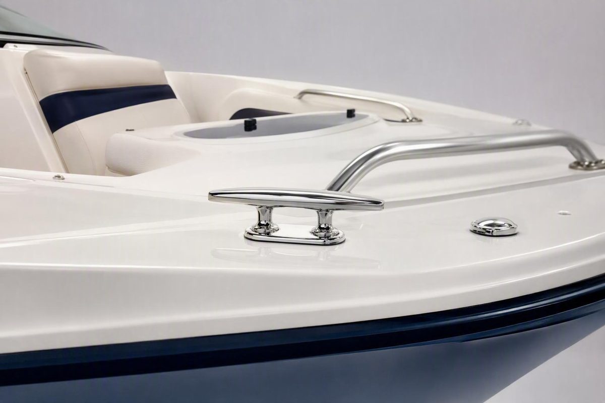
Mounting a cleat on a Bayliner 192 is not simply a matter of drilling a clean fastener pattern. The difficult part is proving that the proposed location can accept and distribute the expected line load without damaging the laminate, contacting concealed systems, or creating a route for water intrusion.
The reviewed evidence does not identify a universal drilling point for every Bayliner 192. This article is therefore a conditional planning guide, not a Bayliner-approved installation specification.
Before making holes, define what the cleat will do, inspect both sides of the proposed mounting surface, identify the substrate, and confirm that the selected cleat can be installed according to its manufacturer’s instructions. For a working docking or mooring cleat, general marine guidance favors corrosion-resistant machine fasteners, locking hardware, and substantial load-spreading backing rather than unsupported screws installed only from above. If the structure or fuel-system clearance cannot be confirmed, do not drill.
Start With the Limitation: There Is No Verified Bayliner 192 Drilling Point Here
None of the reviewed sources identifies a factory-approved cleat location, laminate schedule, reinforcement zone, or concealed-system map for a specific Bayliner 192 model year. A measurement copied from another owner therefore cannot prove that the corresponding point on your boat is safe.
The available Bayliner owner example concerns a 16-foot outboard, not a Bayliner 192. It illustrates real access problems involving flotation foam, confined spaces, and a nearby fuel tank, but it does not provide a transferable mounting location. Treat the 16-foot Bayliner discussion as one anecdotal installation case, not as a model-specific specification.
Before buying hardware or marking holes, record:
- The exact model year and configuration
- The hull identification information
- The proposed bow, stern, or amidships position
- The fitting’s intended use
- The selected cleat manufacturer and model
- The expected directions of line pull
- Photographs of the mounting area from above and below
- The known or suspected laminate construction
- Existing access panels, speakers, compartments, and liners
- Nearby fuel, electrical, control, plumbing, and drainage systems
- The available area for backing hardware and tools
Use this verification hierarchy:
- Prefer documented factory reinforcement. Ask Bayliner or an authorized dealer whether a reinforced position is identified for the exact model year and configuration.
- If no documented position is available, verify the structure directly. Identify the substrate, concealed systems, underside clearance, and a suitable backing arrangement.
- If neither route establishes a defensible installation, stop. Ask a qualified marine repair or fiberglass professional to inspect the location.
Forums, retailer guides, and general marine articles can identify common problems and techniques. They are not Bayliner approval, an engineering calculation, or proof that a particular location can withstand a stated load.
Stop-work checklist
Do not proceed while any of the following remains unknown:
- Whether the substrate is solid fiberglass, cored laminate, embedded reinforcement, or a separate liner
- Whether the proposed bearing surface is structurally suitable
- Whether a backing plate can sit closely and evenly against that structure
- Clearance from the fuel tank, fill hose, vent hose, fuel lines, and fittings
- The location of wiring, control cables, plumbing, and drainage paths
- Whether a proposed service opening would cut a bulkhead, stiffener, or other structural member
- Whether all nuts, washers, backing components, and tools can be installed and later inspected
- Whether a retractable cleat has enough room for its mechanism and required drainage components
Do not convert uncertainty into a weaker fastening method. If a location cannot accept a verifiable installation, reject that location.
Define What the Cleat Will Be Asked to Hold
“Cleat” can describe fittings intended for very different jobs. Separate the proposed use into one of these categories before selecting hardware:
- Supporting fenders
- Organizing or temporarily holding light lines
- Routine docking
- Handling forward or aft spring lines
- Overnight mooring
- Anchoring
- Towing
- Lifting
- Severe-weather restraint
A fender fitting is not automatically a docking cleat. In the 16-foot Bayliner owner case, the lightweight fender fittings were marked “Not for Docking,” while the working amidships cleats received machine fasteners and aluminum backing plates. That distinction is evidence from one owner’s installation, not a Bayliner 192 specification.
If a fitting is described or marked as unsuitable for docking, do not use it for docking, mooring, anchoring, or towing. Place and identify it so another operator is unlikely to mistake it for structural deck hardware.
Foreseeable misuse also matters. A guest, marina employee, or future owner may see a horn-shaped fitting and assume that it can hold a dock line. That possibility favors either a robust installation or an unmistakably light-duty fitting positioned away from normal dock-line leads.
Plan a working docking or mooring cleat as high-load deck hardware. Boat movement, wake, changing dock geometry, and a taut line can impose changing horizontal and vertical components rather than one gentle, steady pull. General marine-fastener guidance consequently favors through-bolting and substantial backing for cleats and other high-load fittings rather than relying on self-tapping screws.
An amidships cleat is useful for spring lines. A forward-leading or aft-leading spring line helps limit fore-and-aft movement while other lines control the boat’s position relative to the dock. That role does not make the cleat suitable for anchoring, towing, lifting, or severe-weather restraint.
Define the intended use in writing. For example:
This cleat is intended for routine docking and spring-line use. It is not intended for anchoring, towing, lifting, or severe-weather mooring.
Obtain confirmation from Bayliner, the cleat manufacturer, an authorized dealer, or a qualified marine professional if the fitting could receive anchoring, towing, lifting, exposed overnight mooring, or other unusually high loads. A generic cleat-sizing formula cannot establish the required Bayliner 192 structure.
Choose the Location by Line Lead, Structure, and Human Factors
Without a verified model-specific mounting point, choose the location by criteria rather than a universal measurement.
A viable location needs:
- Verified reinforcement or enough suitable structure for a backing plate
- A fair and useful line lead
- A fastener arrangement appropriate to the expected pull
- Underside access for installation and maintenance
- Clearance from fuel, electrical, control, plumbing, and drainage systems
- Room for fasteners, washers, nuts, backing, and tools
- Acceptable passenger, boarding, cover, and watersports clearance
Start by mapping the complete line path. Use a temporary line to simulate realistic forward and aft dock attachment points before positioning a drilling template.
Check whether the line will rub against:
- The gunwale or a gelcoat edge
- Windshield frames or supports
- Grab rails
- Upholstery
- Cockpit- or bow-cover fasteners
- Other cleats and deck hardware
- Sharp corners
- Boarding steps, gates, or walk-through areas
A location that appears tidy with no line attached can become unsuitable when the line leads upward, forward, or aft. If the line cannot run fairly, consider another location or a properly installed line-guiding fitting rather than accepting persistent chafe.
The cleat and fastener pattern should also work with the primary load direction. The objective is to carry the expected pull efficiently across the mounting arrangement rather than placing avoidable outward peel on one edge. This does not assume that every load will arrive from one fixed direction; it simply avoids an obviously unfavorable primary lead.
For a proposed amidships cleat:
- Lead a test line forward to a realistic dock attachment point.
- Lead another test line aft.
- Check both leads against the windshield, rails, upholstery, covers, and hull edge.
- Confirm that an operator can handle the line safely.
- Walk the normal boarding route with the lines rigged.
- Test the cockpit or bow cover before finalizing the position.
Human factors matter alongside strength. A fixed cleat can catch feet, clothing, bags, tow ropes, and watersports equipment. It may also obstruct a narrow side deck or create a hard projection in a boarding area.
Compare the main cleat styles:
- Fixed horn cleat: Conventional and mechanically simple, normally requiring only its fastener penetrations. It remains raised and may snag people or gear.
- Folding cleat: Reduces its profile when folded but adds moving parts. It still requires a mounting system appropriate to the load.
- Pull-up cleat: Retracts when not in use but generally needs underside room for studs, retracting legs, washers, and nuts.
- Pop-up cleat: Can reduce snag exposure but may require a larger or more complex opening, internal clearance, and water-management components.
Cleat style determines the hole pattern, underside-access needs, and drainage provisions. Retractable models can pass water below the mounting surface and may need a model-specific waterproofing cup and tubing, according to Boat Outfitters’ general guide to cleat types.
Near a boarding or watersports area, a retractable cleat may reduce snag exposure. That benefit comes with more underside space, a potentially larger cutout, more detailed water management, and a mechanism that must remain serviceable. A fixed horn cleat may be simpler to mount but more intrusive.
Do not let convenient topside space decide the location. A clear patch of fiberglass is unsuitable if the underside is inaccessible, structurally inappropriate, sharply curved, obstructed, or too close to concealed systems.
Inspect Beneath the Proposed Location Before Drilling
Inspect through legitimate existing access before making even a pilot hole. Possible access points include:
- Storage compartments
- Removable trim or service panels
- Speaker openings
- Existing inspection ports
- Access behind removable seating components
- Openings for nearby factory hardware
Use adequate light, a mirror, and, where useful, an inspection camera. The purpose is not merely to find empty space. You must identify the mounting structure, nearby systems, and whether the complete fastening assembly can be installed and maintained.
Look specifically for:
- The fuel tank
- Fuel fill and vent hoses
- Fuel lines and fittings
- Electrical wiring and connectors
- Control and steering cables
- Plumbing and drain hoses
- Flotation foam
- Inner liners
- Bulkheads, stiffeners, and other structural members
- Existing reinforcement
- Existing hardware and backing
- Drainage channels and low points
Fuel-system uncertainty is a stop condition. Do not make an exploratory hole where a tank, hose, vent, line, wire, or cable may be concealed. The owner discussions involving other Bayliner models demonstrate that foam and fuel-system components can obstruct apparently convenient mounting areas, but they do not identify those hazards on a Bayliner 192.
Confirm that the underside offers enough usable bearing area. A backing plate should bear closely and evenly against suitable structure rather than bridging a void, rocking on a pronounced curve, pressing against a liner, or trapping a hose. There must also be enough room to insert the plate, place washers and nuts, and use the necessary tools.
Identify whether the mounting surface is:
- Solid fiberglass laminate
- Cored laminate
- Fiberglass containing embedded reinforcement
- A liner separated from the outer surface
- A combination that changes across the proposed mounting area
Solid and cored fiberglass require different penetration preparation. A cored panel introduces the risk of exposing the core to water and compressing it while tightening the hardware. Embedded reinforcement may improve support, but it must be identified rather than assumed.
Do not infer construction from nearby screws. Factory hardware that appears screw-mounted may engage a concealed block or reinforced zone. An owner discussion about a different fiberglass boat specifically notes that apparently screw-mounted fittings may have hidden backing that cannot be seen from the finished surface.
Create a project record:
- Photograph the underside from several angles.
- Include a ruler or another scale reference where useful.
- Mark the proposed topside position on removable tape.
- Measure the available backing area.
- Photograph nearby hoses, wires, foam, liners, and structure.
- Confirm that every nut will be reachable.
- Save the model year, date, cleat model, and measurements with the images.
If the construction cannot be established non-destructively, ask Bayliner, an authorized dealer, or a qualified marine technician to inspect it. A professional may also be able to determine whether an apparent inner wall is a structural member, removable liner, or appropriate site for a service opening.
If the Underside Is Inaccessible, Create Maintainable Access
For a working cleat, absent underside access is generally a reason to create safe, finished access—not a reason to downgrade automatically to unsupported fasteners.
Possible access solutions include:
- A purpose-made inspection port
- An existing or planned speaker opening
- A removable interior panel
- A covered service opening in a verified nonstructural surface
- Access from a more distant compartment where the hardware can still be reached
A forum discussion about a 2015 Bayliner Element XL—not a Bayliner 192—considered an inspection port or speaker opening as a way to install backing and locking hardware where normal underside access was absent. It is useful only as an example of planning maintainable access on another boat.
Use this sequence:
- Identify a possible service-opening location. It need not be directly below the cleat if the fasteners can be reached safely from another angle.
- Inspect before cutting. Confirm that the opening will not intersect a bulkhead, stiffener, tank component, hose, wire, cable, drain, or other concealed item.
- Test reach. Verify that a hand, backing plate, washers, nuts, and tools can reach the proposed fasteners.
- Select the finished port or cover first. Plan the complete opening and closure before cutting.
- Follow the port manufacturer’s cutting and edge-protection instructions.
- Retain access. The hardware should remain reachable for inspection, leak checks, corrosion checks, and future re-bedding.
Reports from owners of other boats indicate that relatively small openings can sometimes provide enough reach to insert backing plates and tighten nuts. They do not establish a universal opening diameter for a Bayliner 192. Required access depends on the plate, tools, hand clearance, liner depth, and actual structure.
Blind alternatives—including screws, lag screws, toggle bolts, rivet nuts, tapped fiberglass, captured plates, and epoxy plugs—receive conflicting treatment in the reviewed owner discussions. Some may be suitable for expressly light-duty equipment when allowed by the fitting manufacturer and verified against the actual substrate. They are not established as equivalent to a broad, inspectable backing plate with through-bolts for a primary docking or mooring cleat.
One especially uncertain proposal is the foam-cavity epoxy plug: forming a hidden void beneath the fiberglass, filling it with a curing compound, and later drilling or tapping the cured mass. These are anecdotal concerns rather than test data, but they are sufficient reason not to present the method as a general substitute for backed through-bolting.
If safe access and structural backing cannot be achieved, abandon the location. Moving the cleat or hiring a fiberglass professional is preferable to choosing a fastening method mainly because it can be installed from above.
Select the Cleat, Fasteners, Backing, and Bedding as a System
The cleat, fasteners, backing, laminate preparation, and bedding must work as one assembly. Selecting them independently can produce incompatible metals, inadequate thread engagement, inaccessible nuts, or backing that does not fit the verified structure.
Choose the cleat for a defined job
For conventional docking or mooring, a horn cleat is the normal starting point. Cam and clam fittings perform different line-control functions and should not be assumed suitable for primary mooring merely because they can grip a line.
Choose a cleat that accepts the intended dock line and permits a proper cleat hitch. Published formulas relating cleat size to boat length or line diameter are only shopping aids; the reviewed sources offer differing formulas, and none is a Bayliner 192 specification.
Before purchase, obtain the selected manufacturer’s instructions and verify:
- The exact hole or stud pattern
- Fastener diameter and material
- The required number and type of fasteners
- Permitted mounting thickness
- Underside-clearance requirements
- Backing provisions
- Installation orientation
- Bedding compatibility
- Required waterproofing cups, drains, or tubing
- Intended uses and stated limitations
Use structural fasteners for a working cleat
For routine docking or mooring, the commonly preferred arrangement is corrosion-resistant machine fasteners through the cleat and laminate, combined with washers, locking nuts, and substantial load-spreading backing. West Marine’s general guidance treats cleats as high-load hardware that should be through-bolted and backed while also directing installers to follow the hardware manufacturer’s material requirements.
Do not select bolt diameter or length from a generic Bayliner estimate. The fasteners must match the selected cleat, pass through the complete assembly, and provide the engagement required by the specified locking hardware.
Make the backing suit the verified structure
A backing plate spreads load across more laminate than individual nuts or small washers. It is effective only when it bears properly against suitable structure. A large plate that rocks, bridges a void, rests on foam, or presses against a separate liner does not become reliable merely because of its size.
Do not prescribe the plate’s exact footprint, thickness, or material until you have confirmed:
- Laminate type and condition
- Available bearing area
- Cleat fastener pattern
- Intended load and line direction
- Exposure to moisture
- Compatibility with the cleat and fasteners
- Whether the underside is flat enough for proper bearing
- Whether the plate can be inspected and maintained
None is automatically correct for a Bayliner 192.
Dissimilar metals in electrical contact in a wet environment can create galvanic-corrosion concerns. Select the cleat, fasteners, washers, nuts, and backing as a compatible system or use manufacturer-permitted isolation where necessary. General marine guidance warns about dissimilar-metal contact and recommends following the hardware manufacturer’s fastener specification.
Keep every component in its proper role
The assembly’s parts are not interchangeable:
- Machine fasteners clamp the assembly.
- Locking hardware resists loosening.
- Washers provide appropriate local bearing.
- The backing plate distributes load into suitable structure.
- Core-isolation epoxy seals and reinforces the immediate penetration through a cored laminate.
- Flexible marine bedding compound limits water intrusion around the fitting and fasteners.
Sealant is not structural reinforcement. Adhesive under a cleat does not convert unsupported screws into a through-bolted installation, and epoxy used to isolate core does not eliminate the need for suitable load-spreading backing.
Confirm that the bedding compound is compatible with the cleat material, gelcoat, laminate, epoxy-filled penetrations, and future service requirements. Follow its manufacturer’s application, cure, tightening, and cleanup instructions.
Conditional Installation Workflow for Solid or Cored Fiberglass
Proceed only after verifying the intended use, location, concealed systems, substrate, access, and backing arrangement. The following is a conditional checklist, not a substitute for instructions from Bayliner or the manufacturers of the cleat, fasteners, bedding compound, and epoxy.
1. Perform a dry mock-up
Place the cleat or an exact template on removable tape and align it with the intended line lead rather than merely the visual centerline of the gunwale.
Trace the base and mark the hole centers. Before drilling, confirm that:
- The full cleat base sits on a suitable mounting surface.
- Test lines clear the windshield, rails, upholstery, covers, and hull edge.
- The fitting does not obstruct boarding or normal movement.
- The backing plate fits below in the intended orientation.
- Every washer and nut is accessible.
- Tools can reach the hardware.
- No fastener will contact a wire, hose, cable, liner, or tank component.
- A retractable mechanism has enough operating clearance.
- Any required drain has an acceptable destination.
If any item cannot be verified, stop and revise the location.
2. Follow the selected cleat’s hole pattern
Use the cleat manufacturer’s specified pattern, drill sizes, orientation, and installation sequence. Do not substitute generic Bayliner 192 measurements or fastener dimensions.
Control the drilling operation to limit gelcoat damage and unintended penetration. Product-specific drilling methods should come from the cleat manufacturer and, where laminate preparation is involved, the relevant fiberglass or epoxy instructions.
3. Use the correct branch for the verified substrate
For verified solid fiberglass
The general sequence is:
- Drill the manufacturer-specified holes.
- Inspect the exposed laminate and confirm that it matches the prior assessment.
- Clean the holes and mating surfaces as directed by the bedding manufacturer.
- Dry-fit the cleat, fasteners, backing plate, washers, and nuts.
- Confirm that the plate bears evenly and all hardware seats correctly.
- Disassemble the dry fit.
- Apply compatible flexible marine bedding where specified.
- Insert the machine fasteners.
- Install the backing plate, washers, and locking nuts.
- Tighten evenly while observing the cleat, laminate, backing, and bedding.
Do not invent a torque value. Tighten according to the hardware instructions sufficiently to seat the fitting and clamp the assembly without cracking gelcoat, distorting the surface, bowing the cleat, or forcing all bedding from the joint.
For verified cored laminate
Cored fiberglass requires additional preparation so that water cannot migrate into exposed core and tightening does not directly compress it. General marine-fastener guidance recommends removing core locally around the penetration, filling the isolated region with thickened epoxy, allowing it to cure, and redrilling the final hole before bedding and through-bolting.
The conditional sequence is:
- Confirm the core and skin arrangement.
- Open the penetration only as appropriate for that laminate and epoxy system.
- Remove core locally around each fastener position without damaging unintended skins or nearby structure.
- Prepare the cavity according to the epoxy manufacturer’s instructions.
- Fill the isolated region completely with the specified thickened epoxy mixture.
- Allow the epoxy to cure under the manufacturer’s required conditions.
- Inspect the cured isolation area.
- Redrill the final manufacturer-specified fastener holes through the isolated region.
- Dry-fit the complete assembly.
- Apply compatible flexible bedding.
- Install the cleat, machine fasteners, backing plate, washers, and locking nuts.
- Tighten evenly without crushing the panel or starving the bedding joint.
The appropriate opening size, core-removal method, epoxy formulation, cure schedule, and final hole dimensions depend on the actual laminate and product instructions. A forum discussion involving a different cored boat also describes the over-drill, epoxy-fill, and redrill approach, while emphasizing that construction and access control the method for each installation.
If you cannot confidently identify the skins and core, remove core without unintended damage, or verify a complete epoxy fill, have a fiberglass professional perform the preparation. Core isolation protects the penetration; it does not replace the backing plate.
4. Address retractable-cleat drainage
Install the complete system specified for a pull-up or pop-up cleat. If the manufacturer calls for a waterproofing cup, drain fitting, or tube, include it and confirm where the water will discharge.
Do not route drainage onto wiring, upholstery, foam, unsealed core, or into a compartment without an acceptable drainage path. Keep the mechanism and drain accessible for inspection and cleaning.
5. Finish and document the installation
Follow the bedding manufacturer’s cleanup and cure instructions. From below, confirm that:
- The backing plate remains in the intended position.
- Washers and nuts are seated correctly.
- No hose, wire, liner, or other component is pinched.
- The penetrations appear properly bedded.
- No hardware, epoxy, or bedding blocks a drain.
- The service cover does not press against the fasteners.
Photograph the completed backing arrangement before closing the access port. Record:
- Cleat manufacturer and model
- Fastener material and type
- Backing material
- Bedding product
- Epoxy system, if used
- Installation date
- Photographs and measurements
- Applicable manufacturer instructions
Do not use the cleat to lift the boat or subject it to anchoring, towing, severe-weather, or other loads beyond its verified design and intended application.
Commission and Inspect the Installation
Inspect both sides before applying a meaningful line load. The cleat should sit evenly, with no changing gap beneath its base. The backing plate should bear fully against the intended structure, and no wire, hose, liner, foam, or other component should be trapped.
Begin with modest normal use while observing the installation where possible. Do not deliberately shock-load the fitting as a substitute for proper structural verification.
After initial use, inspect for:
- Movement at the cleat base
- Loose or rotating hardware
- A changing gap beneath the fitting
- Bedding loss or failure
- Water intrusion
- Cracked or crazed gelcoat
- Laminate deformation
- Corrosion or discoloration
- Backing-plate movement
- Signs of compressed or damaged core
- Chafe on the line or boat
General cleat guidance recommends checking installations for movement, cracked gelcoat, corrosion, and failed sealant. Follow the cleat, fastener, bedding, epoxy, and backing-material manufacturers’ maintenance instructions rather than applying an unsupported universal torque or tightening interval to every installation.
Reinspect after:
- A hard docking event
- A large wake while tied up
- Severe weather
- An unusually steep line angle
- An incident in which a line snapped taut
- A strike that bent or hit the cleat
- Any evidence of water below the fitting
Stop using the cleat if you find staining beneath a penetration, moisture, a widening base gap, clicking or movement under modest hand pressure, cracked gelcoat, distorted backing, or displaced hardware. Remove the line load and have the installation assessed before further use.
Inspect the dock line as well as the fitting. A secure cleat can still be part of a poor arrangement if the line rubs on fiberglass, a rail, or a sharp edge. Check the complete lead under realistic forward, aft, upward, and downward angles.
Keep the service opening accessible. Maintainable access allows the backing, fasteners, and seal to be checked for leakage, corrosion, displacement, and loosening.
Where exactly should I mount an amidships cleat on a Bayliner 192?
There is no verified universal measurement or factory-approved location in the reviewed evidence. The correct position depends on the exact model year, configuration, underside structure, concealed systems, and intended spring-line leads.
Use a temporary template and run test lines both forward and aft. Look for a fair lead that avoids the windshield, rails, upholstery, covers, and gelcoat. Then inspect underneath for fuel components, wiring, cables, foam, structural members, and enough suitable bearing area for backing.
Prefer a documented factory-reinforced position if Bayliner or an authorized dealer can identify one for the exact boat. Otherwise, rely on direct structural inspection and a properly backed installation. If the substrate or fuel-system clearance cannot be verified, do not drill.
Can I mount a docking cleat with screws if I cannot reach the underside?
Unsupported screws are not established as equivalent to backed through-bolts for a working docking cleat. The preferred solution is generally to create maintainable access through a safely located inspection port, removable panel, speaker opening, or covered service opening.
Before cutting, verify that the opening will not intersect structure, wiring, hoses, cables, or fuel-system components. If proper access and reinforcement cannot be achieved, choose another location or obtain professional help rather than reducing the fastening standard.
Do I need a backing plate, or are large washers enough?
For a working docking or mooring cleat, plan on substantial load-spreading backing unless the boat or cleat manufacturer provides a different verified structural arrangement for that location.
Large washers spread load more effectively than bare nuts but act over less area than a broad plate. Whether washers alone are adequate would depend on verified laminate thickness, construction, reinforcement, fastener geometry, and load information that is not available for a generic Bayliner 192 installation.
The plate must also bear evenly against suitable structure. A large plate resting on foam, a separate liner, or a pronounced curve is not automatically effective.
How should cleat holes be prepared if the Bayliner mounting surface is cored?
First verify that the surface is cored and identify the skin and core arrangement. Do not infer construction from another Bayliner or a nearby factory fitting.
The general isolation process is to remove core locally around each penetration, fill the isolated region with thickened epoxy, allow a complete cure, and redrill the final holes through the cured epoxy before bedding and through-bolting. This is the approach described in general marine-fastener guidance for protecting cored penetrations.
The precise cavity dimensions, removal technique, epoxy mixture, cure conditions, and drilling method must match the actual laminate and product instructions. If you cannot identify or prepare the core confidently, use a qualified fiberglass professional. Bedding alone does not protect exposed core, and epoxy isolation does not replace suitable backing.
Is a pop-up or pull-up cleat better than a fixed cleat near a boarding or watersports area?
A pop-up or pull-up cleat can reduce snag exposure when retracted, which may make it attractive near boarding routes, swimming areas, or watersports equipment. It is not automatically the better installation.
A fixed horn cleat generally requires only its fastener penetrations but remains raised. A retractable model may require larger openings, more underside clearance, access to studs and backing, and a manufacturer-specified waterproofing cup or drain.
Choose by balancing line function, verified structural support, snag exposure, cutout size, underside room, and drainage. If the retractable cleat cannot be installed with its complete manufacturer-specified backing and water-management system, choose another style or location.
Mounting a cleat on a Bayliner 192 is ultimately a verification project rather than a four-hole drilling project. Confirm the exact boat, substrate, concealed systems, line lead, and backing arrangement; follow the selected cleat manufacturer’s instructions; preserve underside access; and stop for Bayliner, dealer, or professional review whenever structural support or fuel-system clearance remains uncertain.