
Measure Twice, Drill Once: Planning a Bow-Mount Installation
Aim to place the deployed shaft near the boat's centerline while keeping the stowed motor head within the hull outline.
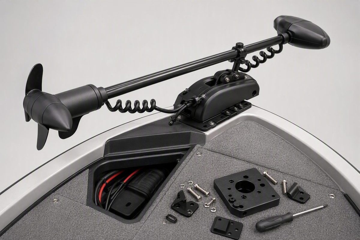
Mounting a trolling motor on the bow is not primarily a drilling job. It is a compatibility, clearance, structural, and electrical-planning job that may eventually involve drilling—if the complete system proves suitable.
Broad layout practices can help you evaluate the project: assemble the motor first, mock up its full movement, protect the stowed head, plan the wiring with the mount, and verify every obstruction before making holes. Exact specifications cannot be generalized.
This is therefore a planning and pre-installation guide, not a substitute for model-specific manuals, hull-specific structural guidance, or qualified marine and electrical work. The safest sequence is measure, mock up, verify, mount, and test. Do not let the irreversible step come first.
Start with the controlling instructions and a stop-work checklist
Collect the manuals for the exact products—not merely the same brand or a visually similar model. Ask the boat manufacturer whether the proposed bow area is approved for the complete motor-and-mount system and attachment method.
For Minn Kota equipment, the company directs owners to the installation section of the applicable motor manual. Its support hub separately covers motor selection, battery and wiring guidance, circuit protection, rigging diagrams, and remote pairing. That separation is a useful reminder that mechanical mounting and electrical rigging are related but model-specific tasks. Consult Minn Kota’s installation and wiring resource hub.
Create a project record before purchasing hardware. Include:
- Boat manufacturer, model, year, hull material, and stated load limit
- Motor manufacturer, exact model, shaft length, voltage, weight, and thrust rating
- Mount or quick-release model and weight
- Total combined motor-and-bracket weight
- Available deck dimensions and bow height above the water
- Proposed mounting side and location
- Documented deck construction and structural support
- Underside access and available working clearance
- Manufacturer-approved fastening and reinforcement method
- Battery type, configuration, weight, and proposed location
- Total positive and negative cable-route length
- Plug, receptacle, breaker or fuse, controls, and sensor locations
- Rail, light, hatch, anchor-locker, and walking-area conflicts
- Transport requirements for the finished system
Record the source of every specification. If you cannot identify which manual or manufacturer supplied a number, do not treat it as an installation requirement.
Stop work before buying hardware or drilling if any of these conditions remains unresolved:
- The deck is cracked, soft, visibly damaged, or shows unusual or undocumented flex.
- The deck construction or structural support is unknown.
- The boat manufacturer has not confirmed that the proposed area is suitable.
- Wires, plumbing, fuel-system components, or structural members may be hidden below.
- There is no confirmed fastening method for the documented deck construction.
- Specified nuts, washers, backing, or reinforcement cannot be installed or inspected.
- A rail must be cut, removed, or welded.
- The motor or bracket obscures a navigation light.
- Shaft length or required propeller depth remains uncertain.
- Electrical voltage, cable sizing, or circuit protection is unresolved.
- A shaft modification or control-head rotation lacks manufacturer approval.
- The boat, motor, mount, and accessory instructions conflict.
Where structural loading, blind fastening, waterproofing, fabrication, or high-current wiring cannot be verified, use a qualified marine installer. A first-person installation account likewise describes professional installation as the ideal approach, even while offering practical advice to owners considering their own work. FishTalk presents professional installation as the preferred approach.
This guide does not provide universal bolt sizes, backing dimensions, torque values, sealants, conductor sizes, breaker ratings, or battery configurations.
Choose the right installation path for the boat and motor
Work through five questions in order:
- Is this a dedicated bow motor or a converted transom motor?
- Does the boat have a documented, manufacturer-compatible mounting surface or plate?
- Can you reach the underside of the proposed mounting area?
- Must the motor be removable for storage, security, transport, or normal boat use?
- Is the bow structure documented as suitable for the complete system?
If you have a dedicated bow motor, an approved deck location, adequate underside access, and no need for frequent removal, a conventional permanent bracket may be the simplest path. The applicable manufacturers must still specify the fastening, backing, reinforcement, sealing, and torque requirements.
If removal matters, consider a compatible quick-release plate. It can simplify storage and may change the bracket footprint or move the motor outward enough to improve bolt access or deployment clearance. Additional reach is not automatically beneficial: verify the plate’s rating, attachment pattern, locking components, deck support, and effect on leverage and the operating envelope.
A clamp-on adapter may avoid permanent deck holes and allow a compatible transom motor to operate from the bow. It is not suitable merely because it fits over the rail. Gunwale width, rail thickness, clamp-screw contact point, hull shape, thrust limit, shaft height, and permitted control-head orientation all matter.
In one first-person review, the examined adapter had a stated maximum rail width of 3 inches and a maximum motor rating of 80 pounds of thrust. The reviewer also reported possible paint damage, a low steering handle when paired with a short shaft, no foot control, and one partial displacement on a V-hull at high power and a particular steering angle. These observations concern one product and one user’s experience, not all clamp-on systems. Read the Pro Controll EZ Mount review and its reported limits.
Manufacturer-specific plates are narrower solutions. Flycraft, for example, states that its bow plate fits only its Stealth X and Guide inflatable models, installs without drilling, supports motors up to 55 pounds of thrust, and works with two identified quick-release brackets. Those product claims do not establish compatibility with other inflatables or boats. See Flycraft’s model-specific plate specifications.
Treat lumber platforms, PVC bushings, cross-brand brackets, and fabricated rail systems as anecdotal adaptations unless the relevant manufacturers or a qualified engineer approve the exact arrangement. Physical fit is not evidence of a dynamic-load rating.
| Installation path | Deck modification | Removability | Rigidity and deployment | Essential compatibility checks | Likely fabrication | Seek professional help when |
|---|---|---|---|---|---|---|
| Permanent bow bracket | Usually requires permanent penetrations | Motor may stow, but the bracket normally remains | Potentially direct and rigid on an approved structure | Deck approval, bolt pattern, underside access, reinforcement, hardware, torque, sealing | Usually limited on a compatible boat | Structure, backing access, or sealing is uncertain |
| Quick-release plate | Base normally remains attached | High, if designed for the motor | Adds another interface and may alter reach or height | Motor and plate match, pin engagement, ratings, footprint, bolt access, stow support | Low to moderate | The plate is being used to bridge unsupported deck area |
| Clamp-on adapter | Usually avoids deck holes | High | Depends on rail geometry and resistance to slipping or twisting | Gunwale width, contact height, thrust rating, hull shape, head rotation, shaft height | Usually low | Clamp contact, hull loading, or resistance to movement is uncertain |
| Manufacturer-specific kayak or inflatable plate | Product-dependent | Often designed for removal | Tailored to particular hull geometry | Exact hull model, motor limit, quick-release model, transport instructions | Usually low | The hull or motor is not explicitly listed |
| Custom platform or rail system | Variable and potentially extensive | Variable | Cannot be assumed without design validation | Structure, dynamic loading, corrosion, access, lighting, controls | High | Structural modification, welding, rail work, or custom supports are required |
Complete the measurement worksheet before positioning the motor
A measurement worksheet prevents the bracket from being evaluated in isolation. Record actual dimensions with the complete bracket, quick-release system, support arm, and accessories—not from catalog photographs.
Include these fields:
- Bracket footprint, including removable panels
- Exact bolt-hole locations
- Usable deck area
- Distance from holes to deck edges and openings
- Underside access beneath every proposed hole
- Space for tools, nuts, washers, backing, or approved blind fasteners
- Bow height above the water under expected loading
- Motor shaft length
- Expected propeller depth in operating conditions
- Fully stowed motor envelope
- Deployment and retrieval arc
- Full steering arc
- Stowed and deployed cable positions
- Plug or disconnect location
- Total battery-cable route
- Battery location and restraint area
- Control, pedal, remote, and sensor locations
Map every potential conflict: bow rails, navigation lights, cleats, anchor rollers, lockers, fish holds, hatches, tie-down points, dock lines, rub rails, trolling-motor supports, and places where people step or brace themselves. Consider the boat both on the trailer and beside a dock. A motor head that appears protected during the mock-up may project into a docking contact zone.
Shaft length, thrust, voltage, battery configuration, and mount compatibility must be selected for the exact hull and expected conditions. The available evidence does not support a universal shaft-length formula.
Do not infer compatibility from brand names. Shaft and bracket dimensions can differ even when product names seem familiar. Informal conversion discussions describe measuring both parts and, in some cases, making custom bushings, but they provide no broad manufacturer approval or verified load rating. A TinBoats discussion illustrates why dimensions must be measured rather than assumed.
For a clamp-on adapter, measure:
- Maximum gunwale width
- Rail thickness
- Outer-hull bracket contact area
- Vertical position where inner clamp screws contact
- Whether contact surfaces are flat, curved, tapered, or flexible
- Clearance for tightening and inspecting the clamp
- Shaft and handle height after installation
Confirm the approved contact and finish-protection method with the adapter manufacturer rather than improvising one.
For kayaks and other small craft, total the weight of the motor, mount, batteries, wiring, connectors, sensor, and associated hardware. Compare that total with the craft’s stated load limit while accounting for the operator and normal gear. Then evaluate fore-and-aft trim; relocating a heavy battery can materially change balance.
Finally, make a no-drill template. Transfer the bracket footprint and hole locations to cardboard, thin hardboard, or another nonstructural material. Mark deck edges, underside obstacles, and required tool access. A template cannot validate the deck structure, but it can reveal conflicts before the motor is positioned or a drill is used.
Choose port or starboard and mock up the complete operating envelope
Neither side of the bow is universally correct. Choose port or starboard by considering:
- Visibility from the helm
- The operator’s usual fishing position
- Which hand or foot operates the controls
- Docking habits and the side normally placed against a dock
- Anchor and line-handling routines
- Hatch and storage access
- Rail and navigation-light locations
- Battery and cable routing
- Safe movement around the bow
Assemble the motor and bracket before marking holes. Include the quick-release plate, support arm, heading sensor, cables, plugs, and other hardware that can affect movement. Place the motor parallel to the selected side in its fully stowed position.
A useful general objective is to place the deployed shaft near the boat’s centerline while keeping the stowed motor head within the hull outline. This is a layout goal, not proof that every off-center installation will handle poorly.
Cycle the system through its complete range:
- Unlock and begin deployment.
- Watch every bracket joint and moving arm.
- Confirm that the shaft passes beyond the bow without contacting the hull.
- Move the motor to its intended operating depth.
- Turn through the complete steering range.
- Retrieve and lock it in the stowed position.
- Repeat the cycle while watching cables, controls, and accessories.
Use a straightedge along the hull side to check whether the stowed head projects beyond the boat’s boundary. View the system from the bow, helm, and normal fishing position.
A specialist retailer’s general guide says brackets are commonly positioned flush with the side or with a slight overhang of less than 1 inch, while also noting that the required clearance varies by motor. Treat that figure only as an example: the exact bracket instructions and a successful full-range mock-up determine the position. Review TrollingMotors.net’s general positioning guidance.
Verify that the finished installation preserves:
- Full navigation-light visibility
- Anchor deployment and retrieval
- Access to lockers, fish holds, and hatches
- Use of cleats and dock lines
- Safe footing and passage around the bow
- Normal cleaning and drainage
- Clearance from ordinary docking contact areas
Once a position passes every check, outline the bracket or template with removable tape. Mark both the accepted stowed position and deployed shaft location. Photograph the setup from above, below, and alongside the hull so it can be reconstructed after the motor is moved.
Mark, drill, seal, and fasten without losing the layout
Use only the drilling pattern, hardware, reinforcement, backing, sealant, edge distances, and torque values approved for the exact boat, motor, and mount. Do not replace missing specifications with generic hardware advice.
Before drilling, inspect both sides of the proposed area. Look for wiring, plumbing, structural members, liners, inaccessible cavities, uneven surfaces, and areas that cannot accept the specified fasteners. If you cannot verify that the drilling path and attachment area are clear, stop and obtain manufacturer guidance or professional assistance.
After the dry fit is approved:
- Return the complete mount to its recorded position.
- Confirm that the template, tape marks, and photographs still agree.
- Mark holes from the compatible bracket or manufacturer-provided template.
- Check every mark against the underside.
- Reconfirm edge clearance and tool access.
- Remove, protect, or isolate anything drilling could damage.
TrollingMotors.net’s general sequence is to drill two pilot holes, secure the mount so it cannot shift, recheck stowed and deployed alignment, and then drill the remaining holes. That sequence may help preserve the layout, but pilot-hole sizes and the order of work must still follow the applicable instructions. See the retailer’s drilling and fastening sequence.
Through-bolts and nuts are one available method where the underside is accessible. Whether the installation also needs specified washers, a backing plate, additional reinforcement, or a different attachment system depends on the deck construction and manufacturer requirements.
Where the underside cannot be reached, do not assume that a blind fastener is equivalent to through-bolting. A blind fastener must be expressly suitable for the documented deck construction and expected motor loads. If no approved method can be confirmed, stop rather than selecting a fastener solely because it fits the cavity.
As practical housekeeping—not structural guidance—cover deep or inaccessible openings before handling small hardware so dropped washers or nuts do not disappear into the bow. Do not let this workaround substitute for adequate access, installation, or later inspection.
Seal every permitted deck penetration according to the boat or mount manufacturer’s procedure and the hull material.
Tighten fasteners only to the specified torque and sequence. Reinstall any removed bracket panels, then check for:
- Deck dimpling, crushing, cracking, or other distortion
- A bracket that rocks or shifts
- Unexplained lateral play
- Incomplete quick-release engagement
- Fasteners that cannot be inspected
- New interference during deployment
- Cable rubbing or pinching
- Loss of hatch, cleat, or anchor access
If the deck begins to deform while the bracket is being tightened, stop. Additional torque is not a substitute for the correct structure, backing, or reinforcement.
Solve limited space, bow rails, and inaccessible hardware without creating a new hazard
When normal placement does not fit, begin with reversible options:
- Reconsider port versus starboard.
- Evaluate a manufacturer-compatible quick-release plate.
- Adjust the bracket within its approved positioning range.
- Choose a motor or mount designed for the available geometry.
- Ask the boat manufacturer about an approved mounting plate or location.
A compatible quick-release system can add useful reach. In one small-boat installation, a quick-release bracket provided about 2 inches of additional reach, creating room for the required bolts and shaft deployment. That is a single installation example, not a standard extension or proof that increasing leverage is acceptable on another boat. FishTalk documents the installation-specific two-inch example.
Verify the plate’s complete footprint, bolt access, rating, locking method, deck support, and effect on leverage. A plate should not be used to bridge an area that the boat manufacturer has not approved for the resulting load.
Bow rails require particular caution. In one center-console installation, the owner cut the rail, altered the motor’s orientation, added a custom long-reach support, and reduced cleaning access beneath that support. The motor still obstructed part of the navigation light’s forward field of view, which the owner identified as unresolved. The rail-equipped installation is a cautionary case study, not a fabrication standard.
Cutting or welding a rail is not a general DIY procedure. That case provides no structural calculations, verified corrosion-control method, or assurance that railing strength and navigation-light visibility were preserved. Any unresolved light obstruction is a stop-work condition.
Preserve practical access as carefully as deployment clearance. The final arrangement must not compromise anchor handling, fish holds, lockers, cleaning, docking, line handling, or safe movement around the bow.
Do not add lumber platforms, PVC sleeves, unverified spacers, or cross-brand brackets merely because they make the dimensions align. Physical fit does not establish capacity or approval.
Use a qualified marine fabricator or installer when the solution requires rail alteration, structural modification, custom supports, uncertain blind fastening, or a mounting platform whose loads cannot be documented.
Plan the battery, wiring, controls, and sensor placement as one system
Mechanical and electrical planning must happen together. Battery position affects load and trim. Cable routing can constrain steering or deployment. A connector can obstruct a hatch. A sensor may require separation from high-current conductors or ferrous objects.
Use the exact motor documentation to determine:
- System voltage
- Number and configuration of batteries
- Permitted battery types
- Required conductor gauge for the complete cable run
- Fuse or circuit-breaker type and rating
- Required circuit-protection location
- Plug and receptacle requirements
- Connection and rigging diagrams
- Maximum cable-run considerations
- Charger compatibility
- Control and networking requirements
Do not copy wire or breaker sizes from another boat. In one installation account, changing motors led the owner to replace a 50-amp breaker with a 60-amp breaker. That example demonstrates model dependence; it is not a recommendation for either rating. Minn Kota’s support index likewise directs owners to model-relevant battery, wiring, circuit-protection, and rigging resources rather than providing one specification for every motor. Use the applicable motor documentation and manufacturer wiring resources.
Secure batteries against movement and use protection appropriate to the craft and operating environment. Account for battery weight in the boat’s load capacity and trim, particularly on kayaks and small utility boats.
Use wiring, connectors, and protected penetrations suitable for the marine installation described by the applicable manufacturer. Route and support cables so they do not:
- Enter the deployment mechanism
- Wrap around the shaft
- Bind at full steering lock
- Rub against sharp deck or hatch edges
- Become a trip hazard
- Carry the mechanical load of a plug or connection
Before working around batteries, isolate power and protect the terminals from tools and loose conductive hardware. Finished energized connections should not remain exposed.
Install a heading sensor according to its own manual. Check the proposed location for interference from batteries, high-current conductors, speakers, and ferrous objects. One installation article used 24 inches of separation as its example, but the correct clearance and test method must come from the documentation for the actual sensor.
If a transom-motor conversion requires rotating the control head, confirm that the motor manufacturer permits the procedure. Track the direction of movement so repeated rotation does not twist internal wiring. Stop if the instructions do not address the proposed orientation.
Apply different rules to conversions, kayaks, and inflatables
A conventional fishing boat, jon boat, kayak, and inflatable do not present the same structure, access, loading, or operating geometry.
Converted transom motors: Verify control-head rotation, shaft length, bracket fit, thrust limit, handle height, cable behavior, steering range, control ergonomics, and manufacturer approval.
Compared with a dedicated bow motor, a conversion may be removable or less expensive. Its drawbacks can include awkward deployment, a handle positioned too low, fewer control options, uncertain bracket compatibility, and greater dependence on improvised parts. A clamp-on review also cautions that repeated head rotation can twist internal wires if the direction is not tracked. See the first-person conversion review and its cautions.
Kayaks: Prefer a hull-specific or manufacturer-compatible bow plate. Adapting a conventional boat motor can create difficult release, stowage, and retrieval problems, especially when the operator cannot safely reach the bow from the seat.
Calculate total installed weight, including the motor, bracket, battery, wires, connectors, and normal angling gear. Assess the resulting trim with the operator aboard. Moving the battery between compartments can materially change fore-and-aft balance. A quick-release bracket can simplify removal, but it does not correct an overloaded or poorly balanced kayak.
A submitted Jackson Kayak installation account illustrates both the usefulness of quick-release hardware and the trial-and-error involved in adapting conventional bow motors, including difficult stowage and deployment. It advises removing the motor for transport in the described setup, but that instruction should not be generalized to every kayak. Read the kayak installation account and its compatibility cautions.
Inflatables: Distinguish manufacturer-specific plates from universal adapters. The Flycraft plate discussed earlier is stated to fit only the Stealth X and Guide families, install without drilling, and support motors up to its stated limit. Its existence does not validate mounting the same motor on another inflatable.
Transport requirements are also system-specific. Flycraft advises against land transport with the motor attached to its plate, while the Jackson Kayak account recommends removal for its described setup. Follow the exact boat, motor, plate, and trailer instructions rather than turning either example into a universal rule. Flycraft states its transport restriction on the product page.
A successful installation on one V-hull, jon boat, kayak, or inflatable proves only that the owner completed that particular setup. It does not establish structural suitability or compatibility for a different hull.
Commission the installation before relying on it
Commissioning begins at the dock or on the trailer with power isolated.
Mechanical checklist:
- All specified fasteners are present and torqued as directed.
- The deck shows no new distortion, cracking, or unusual flex.
- The bracket does not rock or shift.
- There is no unexplained lateral play.
- Quick-release pins or locks are fully engaged.
- Any approved support arm is correctly positioned.
- The motor locks securely when stowed.
- The deployed shaft and propeller clear the hull.
- The shaft reaches the manufacturer-specified operating depth.
- Controls remain accessible.
- Hatches, anchors, cleats, and walking areas remain usable.
- Navigation lights remain unobstructed.
- The stowed head stays within the protected hull outline.
Cycle deployment, retrieval, and full steering repeatedly. Watch every cable through every cycle. Confirm that nothing pinches, twists, wraps around the shaft, or crosses a moving joint.
Electrical checklist:
- System voltage matches the motor.
- Batteries are configured as the manufacturer directs.
- Circuit protection is the specified type and rating.
- Battery terminals and energized connections are covered.
- Batteries cannot move during normal operation.
- Connectors are protected and fully engaged.
- Wiring has the specified support, strain relief, and chafe protection.
- Cable routing is clear of moving hardware.
- No installation work remains exposed or temporarily connected.
Inspect every sealed penetration for visible gaps. After the initial launch, check the relevant compartments for water.
Begin the operational test in calm water at low power. Observe steering, vibration, bracket movement, deck behavior, cable movement, trim, and control response before cautiously increasing power. General kayak-mount guidance likewise recommends checking power, steering, alignment, and connections before launching, followed by an initial calm-water test. Review the general prelaunch and calm-water testing guidance.
Stop testing immediately if you observe:
- Bracket movement
- Cracking or new deck distortion
- Hot wires, plugs, breakers, or connectors
- Repeated breaker trips
- Water entry
- Propeller contact
- Cable pinching or wire twisting
- Navigation-light obstruction
- Unstable trim or handling
- Failure of the stow or deployment lock
Wear a properly fitted life jacket and keep the initial test conservative. Kayaks Hub’s terms page contains the site’s general water-safety notice, including its life-jacket reminder. Read the site’s water-safety notice.
Inspection does not end after commissioning. Before trips—and according to the manufacturers’ maintenance schedules—check fasteners, mount play, deck condition, sealed penetrations, corrosion, wire wear, battery restraint, connectors, quick-release pins, and support components.
The complete process is measure, mock up, verify, mount, and test. Drilling becomes appropriate only after the motor envelope, structural attachment, electrical plan, access, visibility, and manufacturer requirements agree. If any one of those remains uncertain, pause and contact the boat manufacturer, motor manufacturer, or a qualified marine installer. Permanent holes are difficult to reverse; uncertainty is easier to resolve before drilling.
Which side of the bow should a trolling motor be mounted on?
Either port or starboard may be suitable. Choose the side that provides the best combination of helm visibility, control access, fishing position, cable routing, docking protection, and clearance from rails, lights, hatches, cleats, and anchor gear.
Mock up both sides if necessary. Prefer the side that lets the deployed shaft approach the centerline, keeps the stowed motor head within the hull outline, preserves navigation-light visibility, and allows the complete mechanism to operate without interference.
How far should a trolling-motor bracket overhang the bow?
There is no universal overhang measurement. The bracket must extend far enough for the shaft and propeller to deploy clear of the hull while keeping the stowed motor head as protected as practical.
Retailer and first-person installation examples describe anything from a nearly flush position to additional reach supplied by a quick-release plate. Neither approach establishes the correct dimension for another boat. Follow the exact motor and mount instructions and verify the entire operating envelope before drilling.
Can I convert a transom-mount trolling motor for bow use?
Possibly, but only after confirming that the exact motor, adapter, and boat are suitable. A conversion may require manufacturer-approved control-head rotation, adequate shaft length, compatible bracket dimensions, an appropriate thrust limit, safe cable behavior, and a steering handle that remains reachable.
Conversions can be removable and economical, but they may produce awkward deployment, a low handle, fewer control options, uncertain cross-brand compatibility, or clamp movement. Do not improvise a bushing, platform, or head-rotation procedure without approval for the exact combination.
Do I need through-bolts, a backing plate, or special reinforcement?
That depends on the boat’s deck construction, motor and bracket loads, underside access, and the manufacturers’ requirements. Through-bolting is an available method when the underside can be reached, but that alone does not establish the required washers, backing plate, reinforcement, fastener dimensions, or torque.
Do not assume blind fasteners are equivalent to through-bolts. If the approved attachment and reinforcement method cannot be confirmed—or the required hardware cannot be installed and inspected—consult the boat manufacturer or a qualified marine installer.
Can I trailer or transport the boat with the trolling motor attached?
Follow the transport instructions for the exact boat, motor, bracket, quick-release plate, and trailer. There is no universal rule.
Some manufacturer-specific and kayak installations advise removing the motor for land transport. Confirm whether removal, an additional transport support, a locking device, or another precaution is required before towing or carrying the craft.