
How to Position and Secure a Bow Trolling Motor Without Costly Guesswork
Begin with the exact motor documentation, assemble the complete mounting system, test its movement, and inspect the proposed location from both sides of the deck.
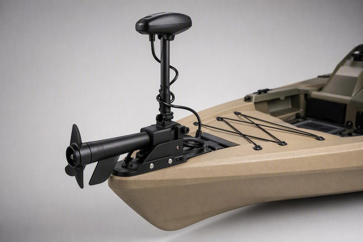
Mounting a bow mount trolling motor is not primarily a drilling job. It is a placement, compatibility, access, and structural-planning job that eventually involves drilling.
The motor must stow without becoming an easy target for docks or pilings, deploy without striking the hull, turn without straining its cables, and attach through every required mounting point to a suitable part of the boat. A fastener location that looks clear from above may still be unusable if wiring, structure, a sealed cavity, or insufficient tool access lies below it.
The safest working rule is simple: do not begin with the drill. Begin with the exact motor documentation, assemble the complete mounting system, test its movement, and inspect the proposed location from both sides of the deck.
This guide provides a conservative pre-drilling workflow rather than a universal installation specification. It does not establish hole spacing, hardware sizes, torque, sealant, electrical ratings, platform dimensions, structural capacity, or regulatory compliance for a particular boat. Those decisions must come from the motor and bracket manufacturers, the boat builder, or a qualified marine installer.
Before You Drill: Gather the Controlling Instructions and Specifications
Start by collecting every document that controls the proposed installation:
- The current owner’s manual for the exact motor model
- The motor’s installation instructions and mounting template
- Instructions for the selected quick-release or sliding bracket
- Instructions for any shaft support, stabilizer, or transport restraint
- Boat-manufacturer guidance for adding deck-mounted equipment
- The wiring diagram for the exact motor voltage and configuration
- Instructions for any heading sensor, foot pedal, network accessory, or remote hardware
Do not substitute a general article for these documents. Minn Kota, for example, directs owners to the installation section of the applicable motor manual and provides separate resources for motor selection, battery wiring, circuit protection, and system diagrams. Its installation and wiring support hub treats shaft length, thrust, voltage, conductor sizing, circuit-breaker sizing, and battery connections as system-specific matters.
Before solving the mounting problem, confirm that the motor itself suits the boat. A well-positioned bracket cannot correct an unsuitable shaft length, thrust selection, or electrical-system voltage.
Create a model-specific worksheet
Complete this worksheet before buying installation hardware or marking the deck:
| Item | Confirmed specification | Controlling document |
|---|---|---|
| Motor manufacturer and exact model | ||
| Steering type | ||
| Shaft length | ||
| Rated thrust | ||
| System voltage | ||
| Motor mounting footprint | ||
| Direct, quick-release, or sliding interface | ||
| Bracket model and current compatibility | ||
| Required mounting fasteners | ||
| Required washers, backing, or load-spreading hardware | ||
| Tightening sequence and torque | ||
| Stowed dimensions and support requirements | ||
| Deployment clearance | ||
| Steering or turning clearance | ||
| Conductor size | ||
| Circuit-breaker rating | ||
| Battery type and configuration | ||
| Plug, receptacle, or connector requirements | ||
| Heading-sensor requirements, if applicable |
Compatibility deserves special attention when the installation includes a removable or sliding bracket. Steering type, motor family, thrust, shaft length, freshwater or saltwater configuration, and heavy-duty model status can affect bracket selection. A third-party bracket guide may help identify the questions to ask, but it cannot prove compatibility; its own guidance recommends confirming the current manufacturer chart and product manual because model lines change. Review the principal bracket-matching factors.
For the generic mechanical work described here, the basic tool list is short:
- Wrench or socket kit
- Phillips screwdriver
- Drill
- Drill bits suitable for the deck material and specified fasteners
Add reversible planning supplies before adding more tools:
- Cardboard
- Painter’s tape
- Fine-tip marker or pencil
- Tape measure
- Ruler or combination square
- Straightedge
- Clamps suitable for temporary positioning
- Flashlight and inspection mirror
- Camera or phone for documenting hard-to-see spaces
Do not infer hole spacing from photographs, choose bolts because they look substantial, or copy another owner’s torque setting. Apply the same caution to sealant, backing plates, blind fasteners, conductor size, breaker rating, and battery configuration. Requirements vary with the motor, bracket, boat construction, and electrical system.
Stop before drilling if any of these questions remains unresolved
- Is the bracket currently approved for the exact motor?
- Can the complete motor stow, deploy, retrieve, and turn without interference?
- Can every manufacturer-required fastener be installed as specified?
- Has the area above and below every proposed hole been inspected?
- Is the supporting structure suitable for the intended installation?
- Are custom platforms, shims, blind anchors, or structural modifications being treated as boat-specific design work?
- Are rail, light, hatch, anchor, trailer, and cover conflicts resolved?
If the answer to any of these is unknown, pause the installation. A different bracket or location may solve the problem; otherwise, obtain guidance from the boat builder, motor manufacturer, or a qualified marine installer.
Choose Direct, Quick-Release, Sliding, or Custom-Platform Mounting
The mounting interface affects more than removability. It changes the deck footprint, fastener locations, stowed position, overhang, height, and sometimes the deployment path.
Direct mounting fastens the motor’s mounting base directly to the boat. It may be suitable when:
- The motor does not need routine removal
- The entire base fits an approved structural area
- Every required fastener location is accessible
- Stowage and deployment clearances are satisfactory
- Service or repair will not create an impractical removal problem
Direct mounting avoids an additional removable interface, but that does not automatically make it stronger or more suitable. The result still depends on the deck structure, required hardware, load distribution, and installation quality.
A quick-release bracket uses a deck-mounted puck or plate and a removable motor-side component. It may be useful when the owner wants to remove the motor for:
- Indoor or seasonal storage
- Transport
- Cleaning
- Maintenance or repair
- Reduced theft exposure
- Unobstructed recreational use of the bow
A quick-release puck can also have a different footprint from the motor base. On some layouts, that difference may move the required fasteners away from an inaccessible cavity or provide usable reach beyond a cramped bow plate.
FishTalk Magazine documented one installation in which a quick-release bracket extended the working position enough to reach mounting surface that the direct motor footprint could not use. That was a solution for one boat, not a universal extension rule, and the author recommended professional installation where the job exceeded the owner’s capabilities. Read the installation account and its limitations.
A sliding bracket adds controlled inboard or outboard adjustment. It can help when one position is needed for operation and another for stowage, trailering, docking, or storage. The slide and its locking mechanism become additional interfaces that must be compatible with the motor and included in every clearance inspection.
A custom platform creates a mounting surface where the boat lacks an adequate bow plate. It may be considered for a small aluminum boat, curved bow, or layout with little usable deck. The platform is not merely a shelf: it becomes part of the load path between the motor and the boat. Its material, supports, attachment points, corrosion management, and interaction with the hull therefore require boat-specific validation.
Community projects sometimes specify particular plywood or aluminum thicknesses. Those figures describe individual builds; they do not establish what is structurally adequate for another boat.
| Arrangement | Routine removal | Security and maintenance | Deck footprint | Extra interfaces | Constrained fastener locations | Compatibility check |
|---|---|---|---|---|---|---|
| Direct mount | Least convenient | Motor remains aboard unless unbolted | Motor-base footprint | No removable interface | Works only if every required point can be fastened correctly | Required |
| Quick release | Usually easiest | Can aid storage, cleaning, repair, and theft prevention | Deck puck may differ from motor base | Adds a removable connection | May relocate the fastening pattern or add usable reach | Essential |
| Sliding bracket | Adjustable and often removable | Can reposition the motor for access or storage | Often larger or longer | Adds sliding and locking components | May move the working footprint | Essential |
| Custom platform | Depends on design | Depends on the selected interface | Boat-specific | Adds a structural platform and its attachments | May bridge to usable structure only when properly designed | Required for motor, bracket, and platform |
Use this decision path:
- Use an approved direct mount when the complete footprint fits, movement is unobstructed, every fastener is accessible, and the supporting structure is suitable.
- Consider a compatible quick-release bracket when routine removal or a different footprint solves a defined problem.
- Consider a compatible sliding bracket when controlled inboard or outboard movement is genuinely required.
- Seek structural guidance for a custom platform when the boat lacks an appropriate mounting surface.
- Choose another location or motor configuration if none of these arrangements permits correct fastening and full clearance.
Do not add an interface simply because it is popular. Every bracket should solve a specific problem and be approved for the exact motor.
Select Port or Starboard Placement by Testing the Whole Boat Workflow
Neither port nor starboard is universally correct. The better side is the one that permits secure fastening and unobstructed movement while preserving the way the boat is actually operated.
Evaluate both sides with a placement scorecard:
| Consideration | Port score or notes | Starboard score or notes |
|---|---|---|
| Visibility from the helm or operating position | ||
| Visibility of motor head, indicators, or controls | ||
| Foot-pedal location and cable path | ||
| Remote-control use | ||
| Right- or left-handed casting | ||
| Fly-line or loose-line management | ||
| Preferred docking side | ||
| Trailer loading and bow-stop clearance | ||
| Push-pole location | ||
| Anchor and bow-roller access | ||
| Hatch and locker use | ||
| Cleats, rails, and navigation lights | ||
| Electrical cable route | ||
| Access below every fastener | ||
| Storage-cover fit | ||
| Walking and casting space |
Skiff owners illustrate why this choice remains personal. In one forum discussion, anglers disagreed about whether the motor should share a side with the push pole, which side best managed stripped fly line, and whether an offset position improved control visibility from the stern. Those reports are useful as workflow prompts, not as controlled performance evidence. The conflicting placement preferences show why fishing habits should not be turned into a universal port-or-starboard rule.
A common placement objective is to put the deployed shaft near the boat’s centerline while allowing the stowed motor to lie generally parallel to one side of the bow. That does not mean the complete base must appear visually centered. An angled or offset base may still place the deployed shaft appropriately.
Next, check exposure. View the stowed motor from above and hold a straightedge along the hull outline. A head, handle, shaft, or bracket that projects unnecessarily beyond that line may be more exposed during docking, trailering, storage, or movement around pilings. Do not apply a generic overhang allowance; the acceptable geometry depends on the motor, bracket, boat, and controlling instructions.
Audit both candidate positions against:
- Bow rails and rail supports
- Navigation lights
- Cleats and chocks
- Anchor lockers, rollers, and handling paths
- Hatches and hinges
- Deck fills and access plates
- Bow eyes, trailer stops, and winch structures
- Covers and cover supports
- Pedal cables and control wiring
- Shaft stabilizers or transport restraints
- Fishing-rod and loose-line paths
- Normal boarding, walking, and casting positions
Do not claim that one side inherently tracks better, saves battery power, or improves efficiency. The supplied evidence does not establish those outcomes. Choose by fit, access, visibility, and workflow.
Test-Fit the Motor in Stowed, Deployed, and Turning Positions
A top-down outline of the mounting base is not a complete test fit. The motor occupies different three-dimensional spaces while stowed, deploying, operating, turning, retrieving, and settling into its cradle.
Assemble the motor and mounting interface according to their instructions. Include every component intended for the final installation: quick-release bracket, slide, shaft support, handle, stabilizer, locking device, and relevant control cables. A specialist retailer’s generic guide also recommends assembling and test-positioning the motor before drilling, while acknowledging that exact requirements vary by motor and boat. See the general test-positioning sequence.
1. Evaluate the fully stowed motor
Check the complete footprint:
- Base and side plates
- Shaft
- Motor head
- Handle
- Steering housing
- Deployment linkages and latches
- Control cables
- Foot-pedal cable
- Shaft support or stabilizer
- Quick-release or slide-locking hardware
Confirm that the motor does not prevent a hatch from opening, occupy essential casting space, interfere with anchor handling, or create an avoidable obstruction. Inspect it from the trailer, dock, helm, and normal fishing positions.
2. Simulate the complete deployment and retrieval path
Move the motor slowly through its full permitted movement. A final deployed position may look clear even though the shaft, head, handle, or linkage hits an obstruction halfway through deployment.
Verify against the model instructions that:
- The shaft clears the bow and hull
- The motor clears rails, lights, cleats, and anchor equipment
- The release or deployment mechanism remains usable
- Cables do not become trapped or pulled tight
- Nearby hatches cannot swing into the moving motor
- The lower unit enters the water on the intended side of the hull
Then reverse the movement. Retrieval may create different conflicts as cables settle and the motor approaches its cradle.
3. Check the deployed position and steering range
With the shaft in its intended operating position, move the motor through the steering range permitted by its instructions. Watch the lower unit and every moving component above the deck.
Look for any point at which a component could:
- Contact the hull or deck edge
- Pull wiring or control cables tight
- Trap a cable beneath the base
- Collide with a rail, light, cleat, or cover fitting
- Prevent access to the controls
- Sweep through a normal standing or casting position
If shaft depth is adjustable, assess the range in which the motor will actually be used. Do not alter or shorten the shaft to correct a clearance problem unless the manufacturer expressly authorizes the procedure.
4. Test the rest of the boat
Open nearby hatches and lockers fully. Operate the anchor system and use the cleats. Stand in normal boarding, casting, and line-handling positions. Check visibility and snag points.
Inspect the boat on its trailer as well. Consider:
- Bow stop and winch-post clearance
- Trailer guides
- Tie-down routes
- Garage or storage clearance
- Boat-cover fit and support poles
- Likely dock-contact points
5. Template irregular surfaces before fabrication
For a small or irregular bow, use cardboard as a reversible prototype:
- Lay cardboard over the proposed platform area.
- Trace gunwales, deck edges, curves, obstructions, and access openings.
- Trim the template until it sits without rocking or covering necessary equipment.
- Mark the complete motor or bracket footprint.
- Position the assembled motor over the template.
- Establish deployment and retrieval clearance before proposing platform fasteners.
- Mark only potential attachment areas that can later be inspected and structurally evaluated.
A community small-boat project demonstrates this planning order—shape the cardboard, confirm deployment and hole placement, and only then transfer the design to permanent material. Its dimensions and materials remain specific to that owner’s boat, not structural specifications for another installation. See the cardboard-platform planning example.
Repeat the entire test after adding or changing a quick-release or sliding bracket. The interface can alter height, footprint, stowed position, overhang, and movement clearance.
Inspect the Deck and Plan Every Fastener From Above and Below
Once a position works geometrically, determine whether the installation can be fastened to suitable structure.
Inspect beneath the proposed mounting area before marking holes. Use existing hatches or inspection openings where possible and identify:
- Electrical wiring
- Navigation-light conductors
- Plumbing and hoses
- Fuel-system components
- Steering or control cables
- Structural members
- Deck-to-hull joints
- Foam-filled or sealed cavities
- Core material or visible evidence of damage
- Previous repairs
- Access to every required mounting point
- Space for the specified tools, nuts, washers, and backing components
Do not assume the visible deck skin is the complete supporting structure. The evidence available here cannot establish whether any particular deck can withstand the loads from a selected motor.
If deck strength, core condition, reinforcement, backing, corrosion isolation, or a platform attachment path is uncertain, obtain guidance from the boat manufacturer or a qualified marine installer. That is especially important when a platform would attach to gunwales, rails, a thin foredeck, or an area not intended for equipment loads.
When the underside is accessible, the retailer installation guide cited above generally favors bolts secured with nuts from below. That generic preference does not establish the correct fastener diameter, material, grade, washers, backing arrangement, thread treatment, tightening sequence, torque, or corrosion control for a particular installation. Those details must come from the controlling documents.
Blind access is not one standardized problem with one standardized solution. Before considering blind hardware, investigate whether a compatible quick-release puck or a different approved position can move every required fastening point into accessible structure.
If blind fastening remains under consideration, the exact hardware must be approved for the selected mounting interface and the boat’s construction, thickness, cavity geometry, and intended load. A fastener is not suitable merely because it fits through the available hole.
Do not operate a mount that has:
- Observable rocking or lateral play
- Missing manufacturer-required fasteners
- Torn or failed isolators
- Partially engaged anchors
- Fasteners installed at unintended angles
- A base attached through only part of its specified pattern
- Visible cracking or crushing around fasteners
- Isolated spacers that appear to create concentrated contact
- Unexplained deck movement
A boating-forum case illustrates the danger without providing a repair specification: an owner described torn isolator components and pulled-out hardware after mounting on a curved bow with an incomplete fastening pattern. Participants proposed conflicting remedies, which is precisely why forum suggestions cannot validate a hull or fastening method. Review the reported curved-deck failure.
Broad load distribution is a design objective, not a backing-plate specification. It does not determine the required material, thickness, shape, or dimensions. Those details depend on the boat and mounting system.
Pause and seek boat-specific guidance when the proposed surface is:
- Curved or sharply crowned
- Thin or visibly flexible
- Cored, with uncertain core condition
- Uneven enough to prevent the base from sitting as designed
- Cracked, delaminated, soft, corroded, or previously repaired
- Located over inaccessible cavities
- Too cramped for the specified tools or backing hardware
- Dependent on isolated point spacers
- Part of an unvalidated custom platform
The appropriate response may be reinforcement, a professionally designed contoured support, a different bracket, another mounting position, or professional fabrication. A stronger-looking bolt does not by itself validate the deck.
Generic Mechanical Mounting Sequence: Mark, Drill, Seal, and Fasten
Begin mechanical installation only after compatibility, movement clearance, structural suitability, underside access, and the plan for every required fastener have been resolved.
This sequence is deliberately generic. The motor, bracket, hardware, and boat instructions control wherever they differ.
-
Protect and inspect the work area. Follow the boat and equipment instructions for protecting components beneath the proposed drilling area. Keep tools and debris away from visible wiring, plumbing, finished surfaces, and inaccessible cavities.
-
Position the verified template or interface. Place the manufacturer’s template, deck puck, or mounting base in the final test-fit location. Secure it against movement using a method that does not damage the boat.
-
Repeat the clearance audit. Before marking anything, recheck stowage, deployment, retrieval, steering, hatches, rails, lights, anchor gear, trailer exposure, and the hull outline.
-
Mark only the specified mounting locations. Use the exact template or base for the selected model. Do not transfer a pattern from another motor or assume apparently unused holes are optional.
-
Verify each mark from below. Reinspect for hidden systems, structure, cavities, and tool access. Confirm that the specified fastening and load-spreading components can be installed at every required point.
-
Follow the documented drilling order. The specialist retailer guide describes drilling two initial locating holes and securing the mount enough to prevent shifting before drilling the remaining specified holes. Use that sequence only when it agrees with the motor or bracket manufacturer’s instructions; otherwise, the manufacturer’s order controls. The generic retailer sequence is described here.
-
Use the prescribed drilling method. Bit type, diameter, drilling depth, surface preparation, and any special treatment for aluminum, solid laminate, or cored construction must come from the applicable boat, motor, bracket, or hardware instructions.
-
Use every required fastening location. If one specified point cannot be accessed or properly installed, stop and revise the arrangement. Do not treat partial fastening as acceptable because the other bolts appear secure.
-
Prepare and protect penetrations as directed. Water-entry protection and any required preparation of cored or laminated material are boat-specific. Use only the preparation method and compatible sealant specified or approved by the boat builder, hardware manufacturer, or qualified installer.
-
Install the specified hardware. Fit the approved fasteners, washers, backing components, isolators, and other load-spreading hardware in the documented orientation.
-
Tighten as documented. Follow the specified sequence and torque. Do not substitute an unrelated generic torque chart. If the base or deck begins to distort, stop rather than assuming additional tightening will correct the installation.
-
Reinstall removed components. Replace any side plates or covers removed to expose the mounting holes, following the motor instructions.
-
Inspect the completed base. Confirm that it sits as designed and has no visible rocking, cracking, crushing, or distortion. This visual inspection does not prove structural adequacy; unresolved questions about the deck or load path still require manufacturer or qualified-installer review.
STOP—do not improvise blind fastening
Do not substitute toggle bolts, rubber isolators, quick nuts, well nuts, spacers, or other blind hardware unless the exact product is approved for the selected mount, deck construction, material thickness, cavity, and intended load.
If every required fastener cannot be installed correctly, change the mounting arrangement or consult a qualified marine installer.
The drill is only one tool in this process. Once the first hole is made, the number of reversible options drops sharply. That is why compatibility, movement, structure, and access must be resolved first.
Solve Rails, Curved Bows, Small Decks, and Other Difficult Layouts
Difficult bow geometry requires more planning, not lower fastening standards.
Bow rails
A rail can interfere with much more than the deployed shaft. Map the movement of:
- Motor head
- Carry or steering handle
- Shaft
- Deployment linkage
- Attachment and locking points
- Quick-release components
- Shaft support
- Control cables
Check the motor while fully stowed, partway through deployment, fully deployed, turning, and returning to its cradle. Preserve the rail’s intended use and keep navigation-light visibility among the unresolved-condition checks.
One boat owner’s forum installation involved cutting and welding a rail, repositioning motor components, and fabricating a custom support. The owner also reported that the finished motor partly obstructed the forward navigation light. That account demonstrates how correcting one interference can create several others; it is not a procedure to copy. See the bow-rail installation and its reported tradeoffs.
Required rail cutting, welding, shaft alteration, or motor modification is a stop condition. Consult the boat builder, motor manufacturer, and a qualified fabricator or installer rather than treating those changes as routine DIY work.
Small bow plates
If a direct mount does not fit, compare three reversible options before drilling:
- A compatible quick-release bracket with a different footprint or usable reach
- A different manufacturer-approved offset or angle
- A properly designed platform attached to validated structure
An angled base can be workable when it permits complete movement, correct fastening, acceptable stowage, and a useful deployed shaft position. The motor does not need to look centered on the bow.
A removable bracket should not be used merely to hide an inadequate deck. It can relocate the holes, but the new fastening points still need suitable structure and correct access.
Curved and uneven decks
Do not assume a collection of isolated spacers can safely level a mounting base. Where a custom support is appropriate, the design objective is generally to provide:
- A lower surface suited to the deck contour
- An upper surface suited to the mounting interface
- Broad contact rather than isolated pressure points
- A validated path for transferring loads into the boat
That describes the problem to solve, not the required material or dimensions. A custom wedge, shim, or platform needs design appropriate to the boat’s construction.
Custom-platform planning
Use cardboard to prototype the layout:
- Trace the available bow area
- Include gunwales, curves, hatches, and rail bases
- Mark the motor’s complete stowed footprint
- Draw the quick-release puck or slide if used
- Simulate deployment and retrieval
- Mark potential boat-attachment points
- Confirm underside access
- Inspect the template from the dock and trailer
- Revise it until the design no longer depends on an unverified hole or unresolved interference
Transfer the shape to permanent material only after the attachment concept and supporting structure have been appropriately evaluated.
If secure bow mounting remains impractical, legitimate alternatives include:
- Professional design and fabrication
- A different approved mounting position
- A motor configuration better suited to the available structure
- Another propulsion or control arrangement
Abandoning an unsuitable bow location is better than forcing a partial or structurally uncertain attachment onto it.
Finish the Electrical Plan and Perform the Final Inspection
Bolting down the motor completes only the mechanical portion. Electrical rigging is a separate task governed by the exact motor, battery, connector, circuit-protection, and boat documentation.
Use the applicable manufacturer instructions to establish:
- System voltage
- Approved battery type
- Number and arrangement of batteries
- Conductor gauge
- Permitted run length or voltage-drop criteria
- Circuit-breaker rating and location
- Plug and receptacle requirements
- Terminal and connector specifications
- Charging configuration
- Wiring diagram for the applicable 12 V, 24 V, 36 V, or 48 V system
Do not transfer an electrical specification from another motor merely because its thrust or physical size appears similar. The manufacturer support hub linked earlier separates battery, wiring, protection, and system diagrams because those requirements vary by configuration.
Before electrical work, follow the exact equipment and boat instructions for de-energizing the system, isolating batteries, and protecting terminals and other energized components. If those sources cannot be identified and followed confidently, use a qualified marine electrician. A FishTalk installation account likewise highlights the need to protect battery terminals from accidental tool contact, although its component choices were specific to one boat.
Plan the cable route against the motor and boat instructions before finalizing the mechanical position. Confirm that the approved route accounts for deployment, retrieval, steering travel, nearby moving mechanisms, deck openings, and required support or protection. Do not invent a universal amount of cable slack; use the allowance required by the motor manufacturer.
If the system includes a heading sensor, follow its current placement and testing instructions. Evaluate the proposed area for the interference sources identified by that manufacturer, which may include batteries, high-current conductors, and ferrous objects. Do not apply one separation distance to every sensor.
Before energizing the motor, complete a final mechanical review against the controlling instructions:
- [ ] The mount has no observable movement against the deck
- [ ] The quick-release or sliding interface locks as designed
- [ ] Every manufacturer-specified fastener is present
- [ ] Hardware was installed in the required orientation
- [ ] The documented tightening sequence and torque were used
- [ ] The deck shows no visible crushing, cracking, or distortion
- [ ] The motor deploys through its complete intended path
- [ ] The motor retrieves and latches as designed
- [ ] Steering movement is unobstructed
- [ ] Cables remain within their prescribed movement range
- [ ] Hatches and lockers remain usable
- [ ] Cleats and anchor equipment remain accessible
- [ ] Navigation lights remain unobstructed
- [ ] Stowed exposure beyond the hull has been evaluated
- [ ] Trailer, bow-stop, dock, storage, and cover clearances are acceptable
- [ ] Any required shaft support or transport restraint is installed
- [ ] Penetrations received the preparation and protection specified for the boat
Any powered startup, deployment cycle, or commissioning procedure must follow the exact motor documentation. As an additional conservative observation step—not a substitute for the manufacturer’s procedure—conduct the first permitted operation in a controlled setting where the mount, bracket, deck, and cable movement can be watched closely. A later low-speed check should occur only if it is consistent with the manufacturer’s commissioning instructions.
Stop using the installation and seek guidance if the observation reveals mount movement, unexpected deck flex, loosening hardware, visible cracking or crushing, contact between the motor and boat, cable interference, or failure of a removable interface to remain locked. These observations indicate a problem; the absence of an immediate problem does not prove structural capacity or long-term safety.
Photograph the finished installation from above, below, and from both sides. Include visible fasteners, backing hardware, penetration areas, cable routes, and the surrounding deck. Baseline images can help identify later visible changes such as movement, cracking, corrosion, staining, or sealant deterioration. They cannot by themselves detect concealed leakage or core moisture.
Use professional help when:
- Deck strength or core condition cannot be confirmed
- Required structural fastening is inaccessible
- A custom load-bearing platform or contoured support is needed
- Navigation-light visibility cannot be preserved
- A rail requires cutting, removal, or welding
- The proposed solution requires alteration of the motor or shaft
- The electrical isolation or protection procedure is unclear
- The completed mount has movement, deck distortion, or incomplete fastening
Drilling is the midpoint of mounting a bow mount trolling motor—not the beginning. A sound planning process starts with exact documentation, confirms compatibility, tests the complete movement envelope, accounts for every fastener and obstruction, and validates the supporting structure through an appropriate authority.
An initial test can reveal faults, but it cannot prove structural adequacy. If the deck, fastening method, rail clearance, light visibility, electrical arrangement, or custom fabrication cannot be validated, the correct next step is a qualified marine installer rather than improvised hardware.
Does a bow-mount trolling motor have to be mounted in the center of the bow?
No. The base does not have to be visually centered. A common objective is to place the deployed shaft near the boat’s centerline while allowing the stowed motor to lie generally parallel to one side of the bow and remain reasonably protected within the hull outline.
An offset or angled installation may be practical if the motor deploys, retrieves, and turns correctly and every required fastener reaches suitable structure. Do not sacrifice fastening access or structural support merely to make the base look symmetrical.
Should I use a direct mount or a quick-release bracket?
Use an approved direct mount when the motor can remain aboard, every required fastener is accessible, and the base has suitable structure and full movement clearance. It avoids an additional removable interface.
Choose a compatible quick-release bracket when routine removal, storage, cleaning, maintenance, repair, theft reduction, or a different deck footprint solves a defined problem. Because the bracket changes the footprint and possibly the motor’s position or overhang, test-fit the complete bracket-and-motor assembly and verify current manufacturer compatibility before drilling.
Neither arrangement is categorically superior. The correct choice depends on the boat, motor, access, and intended use.
How can I mount the motor if I cannot reach the underside of the bow?
First, determine whether a compatible quick-release puck or another approved position can move every required fastener into an accessible area. Ask the boat builder whether an existing or approved access solution permits the specified fastening method.
Do not assume a blind fastener is universally suitable. Any blind-access hardware must be approved for the exact mounting interface and boat construction. If the structure, attachment method, or installation of every required fastener cannot be verified, consult a qualified marine installer rather than partially fastening the base.
Can I build a bow platform for a boat that has no flat mounting plate?
A platform may be possible, but it must be treated as a structural part of the installation. Cardboard can be used to plan its outline, motor footprint, deployment path, hatch clearance, and potential attachment locations before permanent fabrication.
Do not copy material thicknesses or fastener arrangements from an anecdotal project. Platform material, supports, attachment points, load distribution, corrosion management, and interaction with the hull require boat-specific validation. Curved, thin, cored, damaged, or flexible bows are strong reasons to involve the boat manufacturer or a qualified fabricator.
When should a bow-mount trolling motor be installed by a professional?
Seek professional help when:
- Deck strength or core condition is uncertain
- Required structural fastening cannot be reached
- The bow is curved, thin, damaged, or unusually flexible
- A custom load-bearing platform or contoured support is required
- Rails must be cut, removed, or welded
- Navigation-light visibility cannot be preserved
- The installation requires motor or shaft alteration
- Correct electrical isolation, wiring, or protection is uncertain
- The finished mount has movement, deck flex, damage, or incomplete fastening
These are not minor finishing issues. They indicate that the installation depends on structural, fabrication, electrical, or model-specific decisions that should not be resolved through guesswork.