
Choose the Right Automatic Control for Your Bilge Pump
Compare mechanical and solid-state controls by voltage, pump load, mounting fit, activation behavior, bilge conditions and monitoring needs.
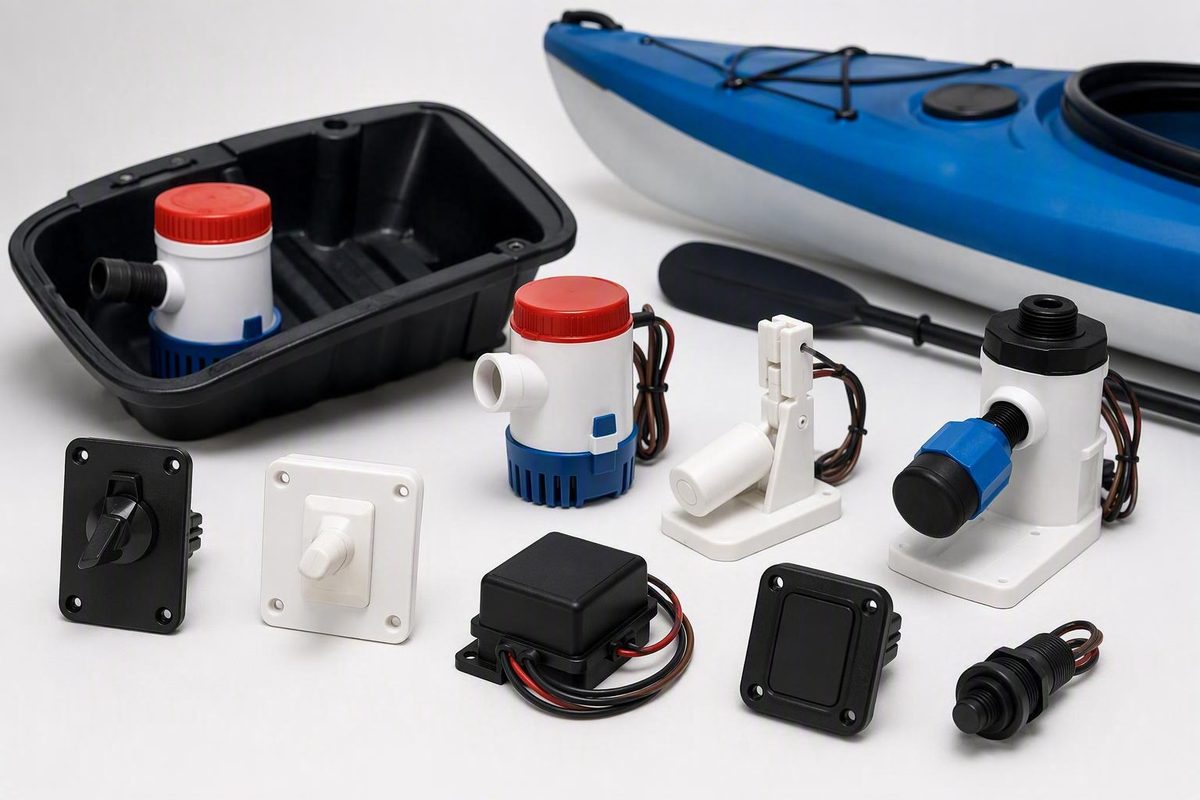
A bilge pump switch can mean a water-level sensor beside the pump, a control switch at the helm, or the switching system built into an automatic pump. Confusing those components can leave you with a part that fits electrically but not physically—or a helm panel that selects AUTO without providing the sensor needed to detect water.
Start with the control architecture rather than the brand. Identify what will sense rising water, what will provide manual control, and which circuit must remain available when the boat is unattended. Then verify the system voltage, pump load, mounting space, activation level, wiring requirements, and documented environmental suitability.
This is a selection, installation-planning, and troubleshooting guide—not a universal wiring specification. The supplied evidence does not establish one fuse size, conductor gauge, relay design, voltage-drop limit, or automatic-feed arrangement for every boat. Those decisions must come from the exact pump, switch, panel, and relay instructions, together with applicable marine electrical guidance or a qualified marine electrician.
The product comparisons below are document-based rather than hands-on tests. No switch can make a bilge system reliable by itself: the battery, circuit protection, wiring, connectors, pump, intake, hose, discharge route, installation, and maintenance all matter. After installation, test the complete system with real water and confirm that water exits the hull.
First identify which kind of switch you need
The term “bilge pump switch” commonly covers three different products:
- Automatic water-level switch: A separate sensor that detects rising water and closes the pump circuit. It opens the circuit after the water falls.
- Helm control panel or rocker switch: The operator interface for selecting manual, automatic, and sometimes complete-off operation. A panel does not necessarily detect water.
- Automatic bilge pump: A pump containing its own float, electronic sensor, or cyclic control rather than relying on a separate external sensor.
An automatic sensor and a helm panel perform different jobs. The sensor decides when the water has reached its operating level; the panel determines which control mode is available to the operator. Both may serve the same pump.
A non-automatic pump normally needs a separate float or electronic sensor for automatic operation. An automatic pump contains internal switching. A three-position panel can provide MANUAL, OFF, and AUTO selection, but AUTO works only when the pump or a separate sensor supplies the automatic function, as outlined in West Marine’s explanation of automatic pumps and panel controls.
Two common control arrangements
Two conceptual arrangements appear frequently in small-boat systems:
- Separately protected automatic feed plus manual helm control: The sensor has a protected automatic-side power feed, while a separate helm switch can run the pump manually. In an appropriate design, either path can energize the pump.
- AUTO-OFF-MANUAL control: A three-position panel supplies the automatic path in AUTO, disconnects the controlled circuit in OFF, and runs the pump manually in MANUAL.
New Wire Marine commercially recommends an ON-OFF manual helm switch paired with a separately fused automatic feed, while acknowledging that an AUTO-OFF-MANUAL arrangement may suit existing wiring or operating needs. Its diagrams illustrate parallel manual and automatic paths, but terminal assignments and indicator behavior vary by hardware, so they should not be treated as universal diagrams in place of the exact equipment instructions.
A separately protected automatic feed is therefore one commercial recommendation, not a universal rule. Whether that feed bypasses the helm panel, a distribution switch, or the main battery switch depends on the vessel’s electrical design and the equipment instructions.
An AUTO-OFF-MANUAL panel provides deliberate complete-off control for service or fault isolation. The operational trade-off is important: OFF may disable automatic pumping when the sensor circuit is routed through that panel. Clear labeling and an obvious indication of the selected mode reduce the chance of leaving automatic operation disabled unintentionally.
A quick buying decision
Use this sequence before searching by price or brand:
- The pump works in MANUAL but a separate sensor no longer starts it: Inspect the sensor, automatic-side feed, connections, panel position, and installed travel before replacing anything.
- A non-automatic pump needs automatic operation: Add a compatible float or electronic water-level sensor and follow the equipment instructions for protection and wiring.
- Automatic operation works but you want helm control: Add a suitable manual or AUTO-OFF-MANUAL panel without assuming that the panel itself senses water.
- An integrated automatic pump has failed: Determine whether its internal sensor is separately serviceable. If not, replacement may involve the complete pump.
- You want independently replaceable parts: A separate pump and sensor may allow either component to be replaced without discarding the other.
- Space is the primary constraint: An integrated pump can reduce the number of separate components, but its total footprint, wiring, intake access, and sensing clearances still require checking.
Write down the exact job the new component must perform. That prevents the most basic purchasing error: ordering a helm selector when you need a water sensor, or adding an external sensor to a pump that already contains automatic control.
How mechanical and electronic switches differ
A conventional float switch uses buoyancy. Rising water lifts a hinged or guided float, closing electrical contacts and starting the pump. As the pump lowers the water, the float falls and the contacts open.
Several designs fit within the broader automatic-switch category:
- Conventional hinged float: An exposed arm rises and falls with the water.
- Covered mechanical float: A housing shields some of the mechanism while allowing water to enter.
- Rolling-ball or microswitch design: Movement changes the position of a ball or applies pressure to an internal microswitch.
- Electromagnetic float: A moving float actuates sealed magnetic or electronic components.
- Solid-state sensor: Encapsulated electronics detect water without an exposed moving float arm.
- Cyclic automatic control: The pump runs periodically or checks motor load to infer whether water is present.
Mechanical-switch strengths and failure modes
A mechanical float offers visible movement, straightforward manual exercising, and independent replacement when it is separate from the pump. These characteristics can make initial fault-finding relatively intuitive.
The float’s travel must remain unobstructed. A hose, wire bundle, pump body, hull structure, loose fastener, leaf, or accumulated debris can stop it from moving fully. A switch may stick on, remain off, or sit where the available water cannot provide enough lift to close it.
Boat movement can also affect some floats. Sloshing or repeated jolting may move the float enough to cause unwanted starts. A float that moves when lifted by hand may still fail under real water conditions if its installed orientation restricts the last part of its travel or provides inadequate buoyant lift.
Rolling-ball and microswitch designs change the contact mechanism but remain motion-dependent. Its electromagnetic model combines a sealed float mechanism with encapsulated electronics, illustrating why “mechanical float” is not one uniform construction.
Solid-state sensors
A sealed solid-state switch has no exposed moving float arm. That may suit a cramped bilge where a hinged float would strike nearby equipment, or an installation where vessel movement repeatedly shifts a conventional float.
Removing the exposed arm does not answer every reliability question. Check the exact documentation for standby current, low-voltage behavior, cleaning procedures, sensing clearances, and any stated limitations involving deposits or contaminated liquid. The supplied evidence does not establish that solid-state sensors last longer than mechanical switches as a class.
The Johnson Ultima is a documented example rather than a universal benchmark. Johnson specifies sealed solid-state electronics, activation at 2 inches, deactivation at 3/4 inch, and a three-second delay intended to reduce starts caused by sloshing. Its published direct-load limit is 20A at 12V but 10A at 24V according to Johnson Pump Marine.
Blue Guard describes the BG-SW as a configurable solid-state option with two integrated sensors, adjustable splash protection, Bluetooth status and testing through an app, and adjustable pump run time. These are manufacturer-described features, not comparative evidence of durability.
What fits which conditions?
Choose according to the installation rather than assuming one technology is categorically superior:
- Accessible, relatively clean bilge with adequate room: A basic mechanical float can be easy to inspect, exercise, clean, and replace.
- Cramped installation: A compact sealed sensor may avoid the sweep area required by a hinged float, provided its mounting and water-level requirements fit.
- Splash-prone or fast-moving boat: A documented delay or adjustable splash setting may reduce nuisance starts, although it cannot guarantee their elimination.
- Debris-prone bilge: A covered float or sealed sensor may reduce some exposure, but every design still needs clear water access and inspection.
- Uncertain contamination: Do not assume that a broad claim about detecting “any liquid” proves performance in oily, fuel-tainted, soapy, salty, or sediment-heavy water.
- Field replacement is a priority: A separate pump and switch can be replaced independently.
- Fewer external components are preferred: An integrated or sealed design may be attractive, but diagnosis and replacement can involve the complete unit.
The useful question is not “Which technology wins?” It is “Which documented failure modes can I inspect, test, and manage in this bilge?”
Match the switch to the pump and electrical system
A switch can fit beside the pump and still be electrically unsuitable. Before buying, complete a worksheet using the pump label, exact manuals, existing wiring information, and switch documentation.
| Pre-purchase item | What to record | Why it matters |
|---|---|---|
| System voltage | Actual DC system voltage | The switch must support the system |
| Pump identification | Manufacturer, model, and part number | Similar pumps may have different loads or wiring |
| Stated running current | Manufacturer value at the system voltage | Must remain within the approved switching arrangement |
| Startup-load guidance | Published starting or inrush information, if available | Starting load may differ from running load |
| Circuit length | Complete positive and negative conductor run | Needed for model-specific conductor and voltage-drop decisions |
| Switch rating | Maximum current at the actual voltage | A headline rating may not apply at every voltage |
| Mounting space | Footprint, height, sweep, and service access | Determines whether the sensor can fit and operate |
| Alarm requirement | None, separate alarm, or auxiliary output | Pump and alarm outputs may have different limits |
| Existing protection | Fuse or breaker type and rating | Must agree with the equipment and conductor requirements |
| Existing connectors | Type, location, and condition | Helps identify work needed before installation |
| Environment | Water exposure, contamination, vibration, and possible vapor risk | Affects the equipment and installation requirements to verify |
Voltage and current are separate checks
A switch marked for multiple voltages is not automatically able to carry the same current at each voltage. Johnson, for example, publishes different voltage-specific limits for the Ultima: 20A at 12V and 10A at 24V. Its electromagnetic float is listed at 15A in the 12V version and 8A in the 24V version on the manufacturer’s switch page.
Other documented examples reinforce the need for model-by-model checking:
- T-H Marine lists its submersible float switch for 12V and 5A on the manufacturer’s product page.
- Johnson publishes the AS888 for 12V, 24V, or 32V with a listed 15A maximum. The supplied page presents that as one cross-voltage rating rather than separate limits for each voltage.
- Blue Guard lists the BG-SW for 12V, 24V, or 32V with a 20A maximum pump output and a separate 1A maximum alarm output.
These are not equal-capability products simply because all are sold as bilge pump switches. They differ in supported voltage, current capacity, sensing method, mounting, and additional functions.
Compare the pump’s published running load—and any available startup guidance—with the switch limit at the actual system voltage. The evidence does not support a universal current-headroom percentage.
If the pump load is too high for direct switching, a relay may be part of a manufacturer-approved design so the sensor controls the relay rather than carrying the motor load. This article cannot supply a universal relay type, contact rating, suppression method, terminal arrangement, or protection scheme. Use only the exact equipment instructions or a circuit designed by a qualified marine electrician.
Do not improvise protection and wiring details
Use the exact pump, switch, relay, and panel instructions to determine:
- Fuse or breaker type and rating
- Conductor size, insulation, and permitted circuit length
- Allowable voltage drop
- Positive and negative routing
- Terminal assignments
- Alarm and indicator connections
- Relay selection and wiring
- Whether the automatic circuit remains energized under the vessel’s normal switch configuration
Do not install a larger fuse merely because the specified fuse opens repeatedly. Commercial troubleshooting guidance recommends replacing a blown fuse only with the same specified amperage and investigating an immediately repeated failure as a possible short, seized pump, overload, or wiring fault rather than reducing circuit protection.
Verify rather than assume marine installation attributes. The exact manuals should address conductor and connector requirements, enclosure or submersibility claims, circuit protection, and any ignition-protection requirement for the mounting location. Product-family marketing language is not enough.
The same precision applies to IP ratings, CE status, ignition-protection statements, ISO references, or standards-related testing. Treat each as an exact-model manufacturer claim unless independently verified; do not transfer a credential from one model to another.
Check mounting fit, water levels, and bilge conditions
Electrical compatibility does not establish mechanical compatibility. A switch can match the system voltage and pump load yet fail to fit the available base, adapter, footprint, height, or fastening arrangement.
Measure the proposed location:
- Flat mounting footprint
- Maximum installed height
- Mechanical float sweep
- Distance to the pump, hose, wiring, strainer, and hull structure
- Access for screws, clips, or adapters
- Access for cleaning and wet testing
- Lowest water path into the sensor
- Distance between the sensor and pump intake
Move flexible hoses and wires through the positions they may occupy underway. A cable that clears a float at the dock can shift when the boat heels or pounds. Do not place a mechanical switch where stored gear or loose debris can fall into its travel path.
Activation and shutoff levels
Activation height is the water depth at which the sensor starts the pump. Shutoff height is the depth at which it opens the circuit. The difference between those levels—often called hysteresis—affects cycling.
A higher activation point permits more water to accumulate before pumping begins. The final residual level also depends on the pump intake and hull shape. A narrow difference between on and off levels can contribute to frequent cycling when discharge water returns to the bilge; a larger difference generally creates greater water-level variation.
Johnson publishes 2 inches on and 3/4 inch off for both the Ultima and its electromagnetic float switch. These are exact-model examples, not default levels for other switches.
West Marine recommends positioning an external float at approximately the level of the pump base to help avoid dry running. Treat that as general retail guidance and follow the pump and switch manuals when they specify a particular position or orientation for the installation.
Orientation, bracket, and adapter restrictions
Check whether the candidate switch is permitted to mount:
- Horizontally
- Vertically
- At a limited angle
- Directly to the hull or bulkhead
- On a detachable base
- On a pump-specific clip
- Through an included or separately purchased adapter
Blue Guard describes the BG-SW bracket as suitable for horizontal or vertical installation. Johnson lists pump-specific interfaces for some of its products: the electromagnetic model is intended for Johnson cartridge pumps and includes an adapter for certain other Johnson pumps, while the AS888 uses a clip-on T-slot. Matching voltage does not make those mounting systems interchangeable.
A delay or splash-protection setting may reduce starts caused by momentary sloshing. It does not correct poor positioning, discharge backflow, or a sensor exposed to routine spray. A delay also means the triggering condition must persist before the pump starts, so its behavior should be assessed during the installed wet test.
Treat performance in oily, fuel-tainted, salty, soapy, or sediment-heavy water as unresolved unless the exact product documentation addresses the relevant condition. A sealed housing alone does not prove that the sensing method will operate correctly through every contaminant or film.
Use this table when comparing candidates:
| Mounting question | Candidate A | Candidate B | Candidate C |
|---|---|---|---|
| Footprint and installed height | |||
| Required orientation | |||
| Mechanical sweep or sensor clearance | |||
| Activation level | |||
| Shutoff level | |||
| Delay or splash protection | |||
| Included bracket, base, or adapter | |||
| Pump-specific mounting restriction | |||
| Lead length | |||
| Stated environmental or enclosure rating | |||
| Access for cleaning | |||
| Access for functional testing |
Unknown entries are not minor omissions. If activation height, permitted orientation, mounting compatibility, or direct-load rating cannot be confirmed, remove the model from the shortlist until the manufacturer or exact manual resolves the question.
Design the controls as layers, not as one switch
A complete bilge-control arrangement can include five distinct functions:
- Primary automatic activation
- Manual override
- Pump-running indication
- Independent high-water warning
- Backup pumping
Combining all five conceptually into “the switch” makes it easier to overlook a missing layer.
Automatic activation and manual override
The primary sensor should start the pump when water reaches its designed level. A manual control lets the operator run the pump deliberately, including while diagnosing the automatic side.
In an appropriate circuit, manual and automatic paths can operate in parallel so either can energize one pump. That is a design concept, not permission to join conductors without a model-specific diagram. The completed circuit must follow the equipment instructions for protection, terminals, indicators, and interaction between the control paths.
AUTO, OFF, and MANUAL labels should be unmistakable. OFF deserves particular attention because it may disable automatic protection in panel-controlled arrangements. Controls should be positioned or guarded to reduce accidental mode changes.
Maintained versus momentary MANUAL
A momentary control runs the pump only while the operator holds it. This reduces the chance of leaving the pump energized but requires the operator to remain at the panel.
A maintained control stays on after selection. It can free the operator to investigate a leak or inspect the bilge, but it increases the importance of a clear running indication and prompt attention after the water has been removed.
Marine surveyor commentary favors clearly identified AUTO, MANUAL, and OFF positions, a conspicuous OFF state, maintained manual operation, protected controls, and optional cycle counting. These are professional design preferences rather than universal legal requirements in the author’s discussion of bilge-control usability.
Pump-running light versus high-water alarm
Depending on its wiring, it may illuminate during manual operation, automatic operation, or both. It does not prove that water is moving through the discharge.
Possible causes include primary-pump failure, a blocked hose, inadequate installed capacity, or incoming water exceeding the system’s removal rate.
Neither device replaces the other:
- A running lamp can reveal frequent or prolonged pump activity before the bilge reaches alarm height.
- A high-water alarm can warn that the water level is not being controlled even if the primary pump appears to be energized.
A cycle counter is another optional monitoring layer. A change in the normal count may reveal backflow, nuisance activation, or a developing source of water, although it cannot identify the cause by itself.
Backup pumping
An elevated secondary pump with its own sensor can provide redundancy if the primary system fails or cannot keep up. It remains a separate design decision involving power, protection, mounting, capacity, and discharge routing—not proof that the primary installation is adequate.
Consider common failure points when evaluating redundancy. Two pumps may offer limited backup value if they depend on the same failed connection, disabled control, or blocked discharge route. Greater separation can improve independence but also adds wiring and maintenance complexity. Use the equipment manuals and applicable marine electrical guidance to determine the appropriate arrangement.
Compare products by verified specifications, not popularity
Product comparisons are useful only when the fields are normalized. A low switch price may exclude the panel, mounting hardware, relay, alarm, or wiring needed for the installation. A premium sensor may add monitoring features that have little value if the pump circuit is unsuitable or inaccessible.
The examples below are not ranked.
| Example | Sensing type | Voltage and published current | On/off levels | Anti-slosh feature | Mounting and wiring notes | Warranty | Alarm/app capability | Listed price and source |
|---|---|---|---|---|---|---|---|---|
| T-H Marine float switch | Mechanical float | 12V; 5A | Not stated | Not stated | Tinned wire and stainless mounting hardware listed | Not stated in supplied evidence | None stated | $10.99; T-H Marine listing |
| Johnson AS888 | Rolling-ball/microswitch float | 12/24/32V; manufacturer lists 15A without separate voltage-specific limits | Not stated | Not stated | Clip-on T-slot for Johnson pumps | Limited 3 years | None stated | No cited price used |
| Johnson Ultima 36303 | Sealed solid-state | 20A at 12V; 10A at 24V | 2 in on; 3/4 in off | Three-second delay | USA version includes a base; pump fit must be verified | Limited 3 years | None stated | $47.99 at Defender; $67.98 at Fisheries Supply |
| Blue Guard BG-SW | Solid-state with two integrated sensors | 12/24/32V; 20A pump output; 1A maximum alarm output | Not stated | Adjustable splash protection | 4.6 × 2.0 in without bracket; horizontal or vertical bracket; six-foot 14 AWG leads | Not stated in supplied evidence | Bluetooth status, testing, and run-time adjustment | $89; manufacturer listing |
The two Ultima retailer prices do not establish that either seller is consistently cheaper. They show why price and stock should be treated as dated commercial snapshots. Fisheries Supply also listed basic and specialized bilge controls across a much broader range, including products above $200 in its bilge-pump category.
Blue Guard’s manufacturer page lists the BG-SW at $89, with 12/24/32V support, a 20A pump limit, 1A maximum alarm output, six-foot 14 AWG leads, a 4.6 × 2.0-inch body without the bracket, and an IP68 housing claim. These are manufacturer specifications and claims, not independent verification of compatibility, certification, or service life for a particular installation.
Read each type of evidence correctly
Product research combines sources that answer different questions:
- Manufacturer specification: Useful for voltage, current, dimensions, terminal functions, activation levels, and stated warranty.
- Manufacturer performance claim: May describe resistance to corrosion, debris, false starts, or contaminated liquid, but does not establish comparative reliability by itself.
- Retailer listing: Useful for a dated price and stock snapshot; technical details may be incomplete.
- Marketplace signal: Ratings, rankings, purchase counts, and badges indicate marketplace activity, not electrical compatibility or service life.
- Owner anecdote: Can illustrate a possible failure mode but cannot establish a product-wide failure rate.
- Independent comparative test: Potentially useful for relative performance, but no controlled long-term comparison is established by the supplied evidence.
A popularity badge cannot show whether a switch fits the pump base, carries the required load, activates at an acceptable depth, or suits the conditions in the bilge. Review totals also combine different boats, wiring practices, environments, and maintenance histories.
Calculate total installed cost
The switch may represent only part of the project cost. Depending on the existing system, installation may also require:
- Helm panel or rocker switch
- Specified circuit protection
- Marine conductor and protected connectors
- Relay, if the approved design calls for one
- Mounting plate, bracket, or pump adapter
- Pump-running indicator
- High-water sensor and alarm
- Replacement hose or discharge fitting
- Professional installation or circuit review
Paying more can be justified when a documented feature solves a real installation problem—for example, a compact sensor where a float cannot move freely or an auxiliary alarm output compatible with the planned monitoring system. Paying more for an app, review count, or popularity badge does not correct a voltage mismatch or poor mounting geometry.
Build the shortlist from the electrical and mounting worksheets. Do not name a “best overall” switch until the boat, pump, circuit, and intended controls define what “best” must accomplish.
Commission and maintain the complete system
Follow the exact pump, sensor, relay, and panel instructions during installation. Commercial troubleshooting guidance advises isolating electrical power before making connections and stopping electrical work if fuel vapor is suspected; address the vapor source and ventilation rather than operating equipment that could create a spark. Use a qualified marine technician when the electrical design or vapor environment is beyond your experience and do not substitute a general article for the equipment manuals.
Commission with real water
A useful commissioning test evaluates the installed system rather than only the loose switch:
- Inspect the installation. Confirm that the pump and sensor are secure, the intake is clear, wiring is supported, connectors are protected as specified, and the hose follows the intended route without kinks.
- Restore power and confirm the selected control mode.
- Add clean water safely. Do not use a liquid that may damage the pump or sensor.
- Observe the activation level. Record the water depth when automatic operation begins.
- Watch the complete start. Look for chattering, brief cycling, delayed starting, or movement of the sensor, hose, or wiring.
- Confirm discharge outside the hull. Motor noise alone does not prove that water is being removed.
- Observe the shutoff level. Record the remaining depth and compare it with the manual where a value is published.
- Check for backflow. After shutdown, determine whether returning hose water immediately restarts the pump.
- Test MANUAL separately. Confirm that the helm control starts the pump without relying on the automatic sensor.
- Restore the intended normal mode. Verify the final switch position before leaving the boat.
If fitted, test the pump-running lamp, high-water alarm, cycle counter, and backup pump independently. An illuminated lamp does not prove discharge, and an alarm test does not prove that the primary sensor starts at the correct water level.
Manually lifting a mechanical float remains a useful component check when the manufacturer permits it. It can show that the mechanism moves and that closing the switch starts the motor. It cannot prove that real water will lift the installed float sufficiently, that activation occurs at the intended depth, or that water reaches the overboard outlet. A forum owner’s report of a float that worked when lifted but failed to rise adequately in water illustrates that possible limitation, but it is an anecdote rather than a failure-rate study from one installation.
Establish a recurring inspection routine
There is no evidence-supported interval suitable for every boat. Usage, storage, bilge cleanliness, climate, and accessibility differ. Establish a routine that includes a pre-trip check when practical and periodic full-water testing.
Inspect:
- Float movement or electronic sensing surfaces
- Debris around the sensor and pump intake
- Mounting screws, clips, bases, and brackets
- Corrosion, heat damage, or looseness at connections
- Chafed, brittle, or unsupported wiring
- Fuse or breaker condition
- Kinked, crushed, loose, or poorly routed hose
- Discharge-outlet obstruction
- Backflow after shutdown
- Pump-running indication
- High-water alarm
- Secondary pump and sensor
Keep a simple log of the test date, activation depth, shutoff depth, unusual sounds, cycle-count changes, and unexpected automatic starts. A shift from the recorded baseline can help expose a developing blockage, backflow problem, connection fault, or new source of water.
Troubleshoot by symptom before replacing the switch
Do not assume that every automatic-operation fault means the sensor has failed. Divide the system into power, control, motor, intake, and discharge functions.
| Symptom | Check first | Other plausible causes | Practical next step |
|---|---|---|---|
| Neither AUTO nor MANUAL works | Battery supply, specified protection, connections, and ground | Failed pump, open conductor, corrosion, seized motor | Follow the model-specific procedure to verify power through the circuit |
| MANUAL works but AUTO fails | Sensor, automatic-side feed, panel position, and connections | Restricted float movement, failed sensor, wrong terminal | Clean and wet-test the sensor, then inspect the automatic path |
| AUTO works but MANUAL fails | Helm switch and manual-side circuit | Failed panel, loose terminal, damaged conductor, incorrect wiring | Trace the manual path separately using the equipment diagram |
| Pump never shuts off | Stuck float or fouled sensor | Wiring error, wet sensing surface, backflow, continuing water entry | Remove obstruction and confirm whether the bilge level is falling |
| Nuisance or rapid cycling | Sloshing and sensor placement | Narrow hysteresis, backflow, incorrect delay setting | Observe multiple real-water cycles and inspect the discharge route |
| Fuse or breaker opens repeatedly | Specified rating and visible wiring condition | Short, seized pump, overload, damaged insulation | Use only the specified replacement and investigate the fault |
| Motor runs but little or no water exits | Intake and overboard outlet | Kinked hose, restriction, excessive lift, poor routing | Clear the restriction and repeat the full-water discharge test |
| High-water alarm activates | Actual level and primary discharge | Primary-control failure, weak supply, blockage, inadequate capacity, major inflow | Treat it as a system warning while locating the water source |
MANUAL works but AUTO does not
If MANUAL starts the pump, the motor and at least part of the supply circuit are functioning. Focus on the automatic sensor, its feed and protection, the panel’s AUTO path where applicable, and the automatic-side connections.
For a mechanical float, remove debris and confirm unobstructed installed travel. For an electronic sensor, use the manufacturer’s wet-test or diagnostic procedure. Do not apply voltage to unspecified terminals or invent a bypass procedure.
The pump runs continuously
Check whether a float is trapped in the raised position or an electronic sensing surface is wet or fouled. Then compare the wiring with the exact diagram to determine whether the sensor has inadvertently been bypassed.
Continuous operation may also reflect real water entry. Confirm whether the bilge level is falling. If it is not, investigate the incoming water and discharge performance rather than concentrating only on the switch.
Backflow can also restart the pump after shutdown. Inspect the hose route, outlet, lift, and any model-approved backflow arrangement.
Nuisance or rapid cycling
Observe enough water cycles to distinguish sloshing from discharge backflow. Check:
- Whether ordinary boat movement reaches or moves the sensor
- Whether the on and off levels suit the installation
- Whether water drains back through the hose
- Whether the sensor sits in a narrow pocket where water surges
- Whether an adjustable delay or splash setting is configured as intended
A delayed sensor may reduce brief false starts but cannot correct a discharge route that returns enough water to reactivate the pump.
Circuit protection opens repeatedly
Replace a blown fuse only with the rating specified for the installed circuit. If the replacement opens immediately, stop and investigate a short circuit, seized motor, overload, damaged insulation, incorrect connection, or pump fault. Repeated operation of the protection device indicates a fault to diagnose, not a reason to increase its rating.
The motor runs but water does not leave the boat
A running motor confirms only that the motor is turning or attempting to turn. Inspect the intake or strainer, the impeller as permitted by the pump instructions, and the discharge hose for obstruction, kinks, crushing, disconnection, excessive lift, or poor routing.
Inspect the through-hull outlet and any approved valves or loops in the route. Installed pumping performance can decline as lift and discharge restriction increase, so a nominal pump rating does not prove actual flow on the boat.
Repair, clean, or replace?
Cleaning may be reasonable when the confirmed fault is removable debris, a lightly fouled sensing surface, or an uncomplicated obstruction and the component remains undamaged. Correct wiring faults only with methods and materials suitable for the location and approved by the equipment instructions.
Replacement is generally more appropriate when inspection finds burned contacts, serious corrosion, broken or water-damaged wiring, a cracked housing, or operation that remains unreliable after proper cleaning and installation correction. Brittle hose, damaged connectors, and failed motors should not be misdiagnosed as switch problems.
Even a correctly operating switch cannot compensate for a weak battery, poor wiring, blocked plumbing, excessive discharge restriction, inadequate pump capacity, or a major leak. Troubleshoot the system as a chain rather than as one replaceable sensor.
Frequently asked questions
Should a bilge pump switch normally be left in AUTO?
When automatic protection is wanted, the intended automatic mode is normally selected, including while the boat is unattended—provided that this agrees with the vessel’s electrical design and equipment instructions. In an AUTO-OFF-MANUAL arrangement, selecting OFF may disable the automatic sensor.
Before relying on AUTO, confirm that the system has passed a full-water test, the circuit is protected as specified, and the automatic path remains powered under the boat’s normal battery-switch configuration. The word AUTO does not by itself prove that the circuit remains energized.
Why does my bilge pump work in MANUAL but not AUTO?
MANUAL operation shows that the pump and part of its supply circuit can operate. The likely search area is the automatic sensor, its protected feed, the panel’s AUTO contacts, automatic-side connections, or restricted float travel.
Check the selected panel position, specified circuit protection, connections, debris, and actual sensor movement. Test an electronic sensor according to its instructions, then finish with a real-water test that confirms both activation and overboard discharge.
Is a solid-state bilge pump switch better than a mechanical float switch?
Not universally. A solid-state switch removes the exposed moving float arm and may suit cramped or motion-prone installations. A separate mechanical float offers visible movement, simple manual exercising, and independent replacement.
The better choice is the documented model that matches the pump’s voltage and load, fits the available space, operates at acceptable water levels, and remains accessible for testing. The supplied evidence does not establish superior comparative service life for either technology as a class.
Can I test a bilge pump switch by lifting the float?
Yes, when the manufacturer permits it. Lifting the float can show that the mechanism moves and that closing the switch starts the pump.
It is not a complete system test. It can miss restricted travel under real water conditions, an unsuitable activation height, backflow, a blocked intake, a kinked hose, or a motor that runs without discharging. Add water safely and verify automatic activation, shutoff, and actual flow outside the hull.
Will a bilge pump keep a boat from sinking?
It should not be treated as a guarantee against sinking. Bilge pumps are intended primarily for normal accumulation and relatively limited water entry. A major leak or hull breach may exceed installed pumping capacity, particularly after accounting for lift, hose restrictions, battery condition, and voltage loss. West Marine likewise cautions that bilge pumps are not dependable protection against major hull damage or large leaks.
Treat the pump as one layer of protection. Maintain the boat and through-hull fittings, investigate unexplained pump activity, carry appropriate emergency equipment, and address the source of incoming water rather than assuming the pump can keep pace.
Conclusion
Choose the control architecture before choosing a product. Narrow the options by actual system voltage, pump load, mounting fit, activation behavior, bilge conditions, and desired monitoring. Treat premium features, retailer rankings, and marketplace popularity as secondary to documented compatibility.
Use exact equipment manuals for circuit design and have uncertain electrical work reviewed by a qualified marine technician. Once installed, test with real water and verify discharge overboard. The right bilge pump switch is the one that fits the complete system and remains straightforward to inspect, test, and troubleshoot.