
A Practical Tour of What You’ll Find Beneath an Outboard’s Cover
Depending on the outboard model, visible parts can include fuel and air hardware, ignition parts, controls, wiring and electronics around the engine block.
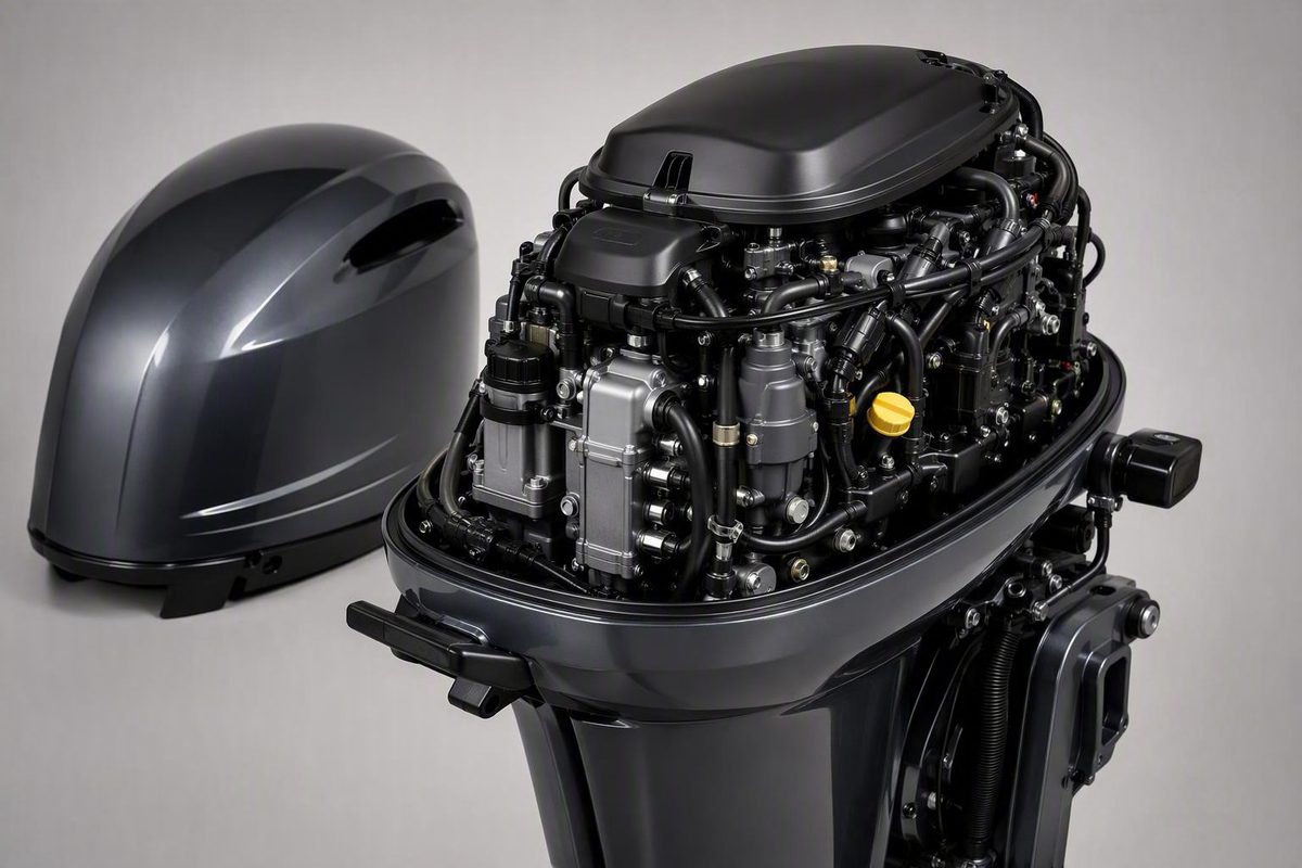
The short answer: the cowl covers the outboard’s powerhead
On an outboard motor, the cowl or cowling is the removable upper cover around the powerhead. Beneath it, you will typically find the engine block or cylinder head and the equipment that supplies air and fuel, produces ignition, responds to controls, and manages electrical functions.
This explanation applies primarily to outboard motors. When boaters ask what is under a marine-engine cowl, they usually mean the removable cover at the top of an outboard.
A quick-reference list of common under-cowl components includes:
- Engine block or cylinder head
- Carburetor or fuel-injection equipment
- Air-intake components
- Spark plugs and ignition wires
- Throttle or choke linkages, where fitted
- Remote-control cables, on some installations
- Wiring, sensors, or electronics, depending on the model
- Cowling seal and latches
These are system categories, not a universal inventory. A small carbureted portable outboard may have relatively simple mechanical hardware, while a fuel-injected model may use more wiring, sensors, protected assemblies, and remote-control connections.
Removing the cowl does not ordinarily expose the pistons and cylinders themselves. It exposes the exterior of the engine assembly—the block or head containing those internal parts—along with equipment mounted around it.
Cowl, powerhead, midsection, and lower unit: know the boundaries
A conventional outboard has three major sections: the powerhead, midsection, and lower unit. The cowl surrounds the upper powerhead rather than covering the entire motor, as shown in this overview of outboard anatomy.
The powerhead contains the engine and its associated operating equipment. It normally remains above the water while the outboard is running. Depending on the model, visible components can include fuel and air hardware, ignition parts, wiring, controls, and electronics arranged around the engine block.
The midsection connects the powerhead to the lower unit. It carries or encloses the tubes, hoses, cables, shafts, and exhaust paths that travel between those sections. The engine’s mounting structure is also associated with this central portion.
The lower unit contains the gearbox, propeller shaft, propeller, cooling-water intake, and skeg. These components are below the powerhead and are not under the upper cowl.
One detail can seem counterintuitive: although the powerhead does not normally go underwater, cooling water circulates through passages in the engine block. Water enters through the lower-unit intake and travels upward through the cooling system. That connection does not make the intake an under-cowl component; it means the cooling system spans more than one section of the motor.
A useful generic illustration should show:
- A removable upper cowl surrounding the powerhead
- A callout for the powerhead and engine assembly
- A visibly separate midsection
- A visibly separate lower unit
- Lower-unit callouts for the water intake, gearbox area, propeller shaft, propeller, and skeg
- A simplified pathway showing cooling water moving from the lower unit toward the engine
Such an illustration should remain schematic. The positions of carburetors, injection equipment, spark plugs, electronics, and cables should not be presented as universal unless the drawing depicts a named engine model.
The main parts you may see after removing the cowl
The most reliable way to understand the area beneath a cowl is by system, not by memorizing a single photograph. Manufacturers package the same broad functions differently, and layouts can change with horsepower, model year, fuel system, and engine design.
Engine assembly
It contains the cylinders and pistons as internal parts. From outside, you may see cast surfaces, covers, fasteners, hoses, wiring, and equipment mounted around the assembly.
Some engines also have guards or secondary covers over parts of the powerhead. Their names and purposes cannot be determined reliably from shape or position alone. Use the exact model’s parts diagram before assigning a component name.
Fuel delivery and air intake
A carbureted outboard has one or more carburetor assemblies that mix incoming air and fuel. Depending on the layout and surrounding covers, recognizable features may include the carburetor body and mechanical linkages attached to it.
A fuel-injected outboard uses fuel-injection equipment instead of a carburetor. Sensors, wiring, and other electronic equipment may also be present, but their identities and locations depend on the engine. A generic guide cannot reliably label every hose, connector, or housing.
Air-intake hardware may be visible near the fuel-delivery equipment.
Fuel-delivery equipment should not be confused with a fuel tank. A carburetor or injection system meters and delivers fuel; a tank stores it. Some portable motors may have both beneath the cowl, while many outboards receive fuel from a separate tank elsewhere in the boat.
Ignition system
Spark plugs and ignition wires are common under-cowl components on gasoline outboards. The number and arrangement of plugs depend on the engine’s cylinder count and design, and surrounding equipment may partly obscure them.
An ignition wire leads to a spark plug, but not every electrical lead is an ignition wire. Engines may also have connectors, wiring harnesses, and sensor leads.
Controls and linkages
On a carbureted motor, throttle and choke linkages may be visible where they attach to the carburetor. Their positions vary with the engine design and control setting, so a linkage cannot be judged against a generic photograph alone.
Small portable engines may integrate controls with a tiller or place them directly on the motor. Larger remote-controlled outboards may have steering or throttle-control cables entering the cowling. To identify a cable’s exact function, trace it against documentation for the specific engine rather than relying only on where it enters the powerhead area.
Wiring, sensors, and electronics
Some models place sensors and other sensitive electronic equipment beneath the cowl. Wiring looms, connectors, protected boxes, and covered assemblies are therefore model-dependent and should not be assigned precise names without supporting documentation.
Positive identification requires the manufacturer’s parts diagram for the exact engine designation, not merely a photograph of another outboard with similar horsepower.
Cowling hardware
Removing the cover also reveals parts of the cowling interface, including its latches, vents, and perimeter gasket or seal. These parts do not produce combustion, but they help secure the cover and protect the equipment it encloses.
Generic diagram legend
A non-model-specific diagram should use numbered system categories rather than fixed component positions:
- Engine assembly — block or head containing the cylinders and pistons
- Fuel delivery — carburetor or injection equipment
- Air intake — visible intake hardware and air pathway
- Ignition — spark plugs, plug leads, and related wiring
- Controls — throttle or choke linkages where fitted
- Wiring or electronics — model-dependent harnesses, sensors, and protected equipment
- Cowling seal — gasket between the removable cover and lower casing
This approach explains what each system does without implying that every outboard uses the same physical map.
Carbureted versus fuel-injected: why two cowls can hide different hardware
The fuel system is one of the clearest reasons two outboards can look different beneath their cowls.
A carburetor mechanically mixes incoming air and fuel. On a carbureted outboard, the carburetor and attached choke or throttle linkages may be recognizable. The arrangement can be relatively easy to follow on a small portable motor, although covers and compact packaging may obstruct the view.
A fuel-injected engine uses injection equipment instead of a carburetor. It may also have model-dependent sensors, wiring, and electronics associated with engine operation. However, the term “fuel injected” does not establish where each component is mounted or identify every line, connector, pump, filter, or housing.
The absence of an obvious carburetor may suggest an injected engine, but appearance alone may not provide a positive identification. A carburetor can be partly hidden, and unfamiliar intake hardware can be mistaken for fuel equipment. Check the model designation and compare the engine with its manufacturer documentation.
| Configuration | Commonly supported under-cowl equipment | Model-dependent items | What not to assume |
|---|---|---|---|
| Carbureted | Carburetor, intake hardware, spark plugs and ignition wiring; possible choke and throttle linkages | Number and position of carburetors, covers, and cable routing | That every visible lever has the same purpose or position |
| Fuel injected | Injection and intake equipment, spark plugs, and ignition wiring | Sensors, electronics, connectors, housings, and component locations | That every line or electrical box can be identified without the model diagram |
| Either configuration | Engine block or head, controls, wiring, and cowling seal | Built-in tank, remote-control cables, and protective covers | That every listed component will be immediately visible |
Identification should stop at what the available documentation supports. A generic article is not a basis for changing adjustments, operating unfamiliar linkages, or opening electrical or fuel-system connections.
Two-stroke versus four-stroke: differences in lubrication and internal design
Both two-stroke and four-stroke outboards contain fundamental internal parts such as pistons and cylinders. The terms describe how the combustion cycle is completed and are also associated with different lubrication arrangements.
A four-stroke completes intake, compression, combustion, and exhaust over four piston strokes, while a two-stroke completes its operating cycle in two piston strokes, according to this comparison of two-stroke and four-stroke outboards.
A four-stroke outboard has an internal oil supply and sump. That does not mean removing the cowl will reveal a clearly separate tank: much of the lubrication system is integrated into the engine, and its visible features vary by design.
Two-stroke lubricating oil is consumed during operation and must be replenished. Storage and delivery arrangements vary, and an external oil supply may be elsewhere in the boat. An oil tank should not be assumed to sit beneath the cowl.
| Point of comparison | Two-stroke | Four-stroke | What the distinction does not prove |
|---|---|---|---|
| Operating cycle | Completed in two piston strokes | Completed in four piston strokes | Where every visible component is mounted |
| Lubrication | Oil is consumed and replenished | Uses an internal oil supply and sump | That either system has an obvious under-cowl tank |
| Oil storage | Arrangement varies and may involve external storage | Lubrication supply is integrated with the engine | Exact filler, line, sump, or reservoir position |
| Component visibility | Depends on model packaging and covers | Depends on model packaging and covers | Accessibility, weight, or complexity |
| Identification | Confirm through model information | Confirm through model information | That appearance always provides a certain answer |
Broad statements that every two-stroke is lighter or simpler than every four-stroke are not reliable identifiers. Horsepower, generation, injection technology, and manufacturer design can all affect what is present and visible.
For an under-cowl observer, the practical distinction is narrower: engine cycle affects internal operation and lubrication, but it does not provide a universal map of tanks, lines, or other components.
Fuel and oil tanks: what may be under the cowl and what may be elsewhere
A fuel or oil container may be associated with the area under an outboard cowl, but neither should be assumed.
Many outboards under five horsepower have internal fuel tanks, while larger engines commonly draw from external tanks; this is a general orientation point rather than a rule for every motor in either category, as the outboard anatomy guide explains.
A built-in fuel tank stores fuel. It is functionally separate from the carburetor or injection equipment that meters and delivers fuel to the engine. If an under-cowl container is present, use the model’s fuel-system diagram before deciding what it holds.
Larger outboards commonly draw fuel from a separate tank elsewhere in the boat. Fuel lines carry that fuel to the delivery equipment beneath the cowl, but the remote tank itself is not under the upper cover.
Oil arrangements require equally careful identification:
- A four-stroke has an internal oil supply and sump, though these may not resemble a separate reservoir.
- A two-stroke consumes lubricating oil, but storage and delivery vary.
- A two-stroke oil tank may be external and located elsewhere in the boat.
| Item or arrangement | Could it be under the cowl? | Could it be elsewhere? | How to confirm |
|---|---|---|---|
| Small portable fuel tank | Yes, on some models | Yes; not every portable uses an internal tank | Check the model’s fuel-system diagram and filling instructions |
| Remote fuel tank | The tank itself is not under the cowl | Yes, elsewhere in the boat | Check the documented tank arrangement and fuel-line route |
| Four-stroke oil supply | The lubrication system is within the engine, though it may not appear as a separate tank | Generic guidance does not establish a separate remote tank | Use the specified inspection points in the model documentation |
| Two-stroke oil arrangement | Possibly, depending on the design | Yes, external storage may be used | Check the exact oil-system documentation |
Horsepower provides context, but the make, model, year, and configuration determine the actual arrangement.
The cowl is functional: protection, airflow, seals, and access
An outboard cowl is more than a decorative shell. It protects the powerhead and sensitive components from spray, salt, sand, sunlight, residue, and other contaminants. At the same time, the engine requires air, so the cover cannot function as an ordinary sealed box.
The cowling must admit or channel intake and ventilation air while helping keep water away from the intake and enclosed equipment. Vents and ports provide airflow routes, but their number and placement are model-dependent. This combination of engine protection, air admission, and water exclusion is part of the basic function of an outboard cowling.
A rubber perimeter gasket or seal commonly sits where the removable upper cowling meets the lower engine casing. It helps limit moisture and salt-spray intrusion. If damaged or displaced, the seal may allow spray or salt crystals to reach the engine head or sensitive electronic equipment, although visible deposits do not by themselves prove a particular entry path or mechanical fault, as this cowling overview notes.
The top cowling commonly detaches from the lower housing using two or three latches, but the latch count, style, sequence, and removal method vary by engine. The same cowling overview supports that general description.
Removability provides access for inspection and repair, but it does not create a universal removal or operating procedure.
How to approach an under-cowl inspection without guessing
Treat cowl removal as limited visual orientation, not as a generic repair, adjustment, cleaning, or diagnostic procedure.
Before trying to identify components, record:
- Manufacturer
- Model designation
- Rated horsepower
- Model year or serial information
- Whether documentation identifies the engine as two-stroke or four-stroke
- Whether documentation identifies it as carbureted or fuel injected
Consult the exact owner documentation before removing the cowl. The manual should determine the required shutdown or cooling precautions, the correct cowl-release method, permitted inspection steps, and reinstallation procedure. The available general sources do not establish one safe procedure for every outboard.
After removing the cover in accordance with that documentation, compare what you see with the manufacturer’s parts diagram. Begin with broad categories—engine assembly, intake, fuel delivery, ignition, controls, wiring, and seal—then use the diagram’s labels to narrow the identification.
A limited visual check can record:
- Obvious moisture
- Salt crystals or residue
- Visible corrosion
- A perimeter seal that appears displaced, pinched, torn, or damaged
- Cowling latches that appear loose or do not secure normally
- A visibly disconnected part
These observations are not diagnoses. Moisture or corrosion does not establish when, where, or why exposure occurred, and the appearance of a component may not reveal its intended configuration. If the model documentation does not explain what you see, qualified service may be appropriate.
This article does not establish procedures for operating linkages, disconnecting wiring or hoses, opening fuel-system components, testing ignition systems, applying cleaners or treatments, or running an engine with its cover removed. Those actions depend on model-specific manufacturer instructions and appropriate service precautions.
The practical answer is straightforward: beneath an outboard cowl is the powerhead and the equipment that lets the engine take in air and fuel, ignite combustion, respond to controls, and manage sensitive systems. A general guide can help identify broad component groups and distinguish the powerhead from the midsection and lower unit. Exact labels, removal steps, inspection limits, and service procedures must be matched to the engine’s make, model, horsepower, and year.
Frequently asked questions
Is a marine-engine cowl found only on an outboard motor?
No. “Cowl” or “cowling” is a general term for a removable engine covering and can be used in other vehicle and engine contexts. In everyday boating usage, however, a marine-engine cowl usually means the removable upper cover of an outboard. Inboards, sterndrives, and electric propulsion systems may instead use engine boxes, hatches, covers, or housings with different layouts.
Are the gearbox, driveshaft, and propeller under the upper cowl?
No. The upper cowl surrounds the powerhead. The midsection carries connecting shafts and other services between the engine and lower unit, while the gearbox, propeller shaft, propeller, water intake, and skeg belong to the lower-unit area. A driveshaft and a propeller shaft are distinct parts, but neither should be treated as equipment enclosed by the upper cowl.
Do all small outboards have a fuel tank beneath the cowl?
No. Some small portable outboards have a built-in under-cowl fuel tank, but the arrangement is not universal. Other small motors use separate tanks. Horsepower is only a clue; consult the manufacturer documentation for the exact model.
Can I tell whether an outboard is carbureted or fuel injected by looking under the cowl?
Sometimes. A visible carburetor with choke or throttle linkages strongly indicates a carbureted engine, while an injected model uses fuel-injection equipment instead. Covers and unfamiliar packaging can make visual identification uncertain, so confirm it using the model designation and manufacturer’s parts diagram.
What does the rubber seal around an outboard cowling do?
The perimeter seal helps close the joint between the removable upper cowling and lower engine casing, limiting moisture and salt-spray intrusion. If the seal appears displaced or damaged, consult the model documentation; visible moisture or deposits alone do not prove a specific fault.