
Measure the Motor, Match the Transom, and Avoid the Wrong Shaft
For a gas motor, measure from its bracket seat to the anti-ventilation plate. For boat sizing, measure mounting surface to hull or keel at the motor centerline.
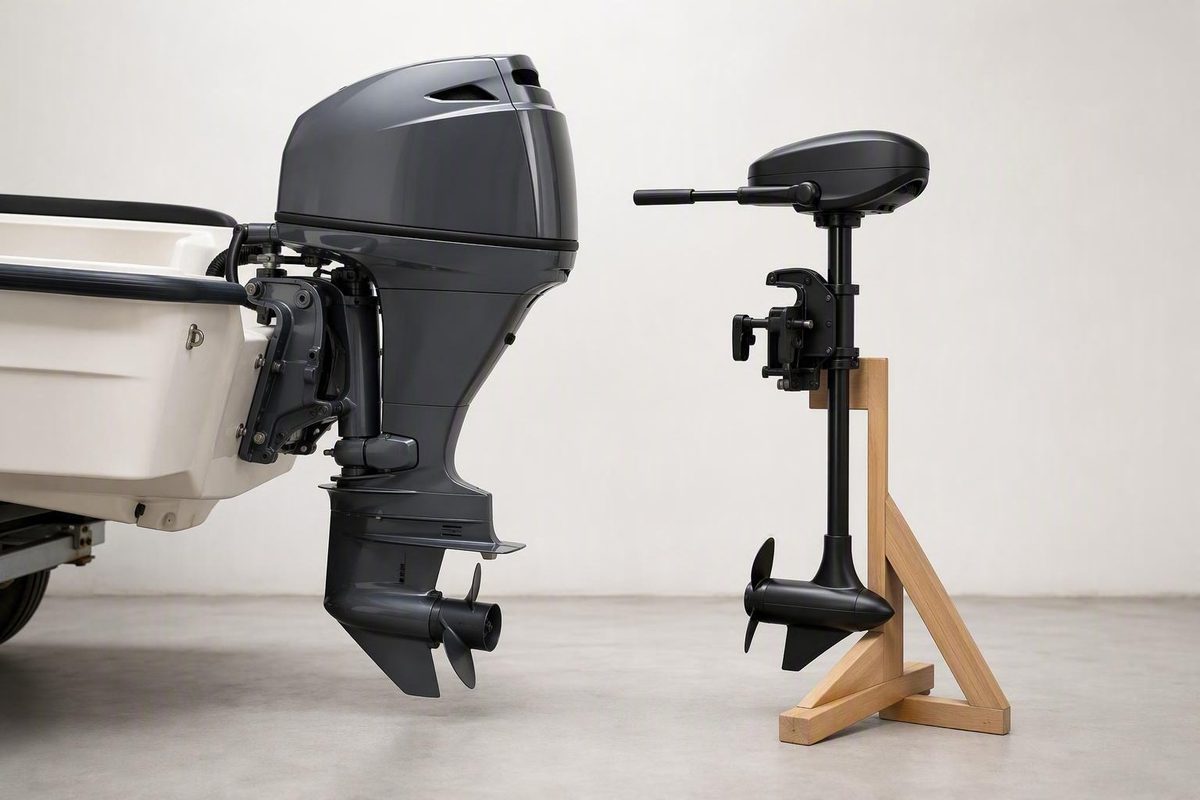
By Nora Whitby · Documentation reviewed August 13, 2026
First decide what you are measuring
“How to measure outboard shaft length” can describe two different jobs:
- Measure an existing outboard to identify whether it belongs to a short, long, XL, or another nominal shaft class.
- Measure the boat to select an outboard that suits its transom or motor bracket.
These measurements are related, but they are not interchangeable. Measuring the motor describes its mounting-to-lower-unit geometry. Measuring the boat describes the height the installation must accommodate.
For a conventional combustion outboard, the quick method is to measure vertically from the mounting-bracket surface that rests on the transom to the anti-ventilation plate above the propeller. To size a motor for a boat, level the boat and measure at the intended motor-mounting centerline from the top mounting surface to the relevant bottom of the hull or keel. A separate motor bracket changes the upper reference point because the motor rests on the bracket rather than the original transom top (Suzuki Marine’s shaft-length and mounting guidance).
Before placing the tape, identify the propulsion type. Some electric-outboard manufacturers measure to the center of the propeller, whereas conventional combustion outboards are commonly measured to the anti-ventilation plate. Applying the wrong convention can produce a credible-looking number that does not correspond to the manufacturer’s advertised shaft option.
Use this three-check sequence:
- Motor check: Measure the existing motor using the endpoints specified for that propulsion type and model.
- Boat check: Measure the boat at the location where the motor will actually be supported.
- Installation check: Confirm the final mounted position against the boat builder’s and motor manufacturer’s instructions.
A generic measurement can screen possible options, but it should not be the sole basis for buying a motor or drilling permanent mounting holes. If the current model documentation provides a specific diagram, tolerance, mounting range, or hull reference, that instruction controls.
Know the reference points and terminology
The transom is the rear mounting surface of the boat. On a directly mounted, single-engine installation, measure at the intended motor-mounting centerline—not at a transom corner where the hull geometry may differ.
On the motor, the upper reference is the mounting or clamp-bracket surface that actually seats on the transom or separate bracket. It is not the top of the cowling, carry handle, steering arm, or clamp screw.
The lower reference on a conventional combustion outboard is generally the anti-ventilation plate, the horizontal plate immediately above the propeller.
Published instructions do not all use the same surface of that plate. ePropulsion’s combustion-outboard diagram specifies the bottom of the anti-ventilation plate (ePropulsion’s combustion and electric measurement comparison).
Suzuki’s general guide instead describes measuring to the top of the plate. Record the exact endpoints you used and let the manual for the particular motor settle the convention. A small difference caused by using the other plate surface does not, by itself, prove that the motor belongs to a different shaft class.
A basic toolkit is enough:
- Rigid tape measure
- Straightedge, carpenter’s level, or straight board
- Pencil or removable marker
- Notepad or phone for recording the result and endpoints
- Helper when access is awkward or the motor cannot be measured securely by one person
A flexible tape can sag or follow the curve of the gearcase. The objective is a straight vertical dimension, not the distance along the motor housing.
How to measure a conventional combustion outboard
Leave the outboard securely mounted on the boat when practical. If it must be measured off the boat, support it using the handling and stand procedure specified for that model; do not improvise support for a heavy motor. Position the motor upright enough to take a true vertical measurement.
Then follow these steps:
- Find the transom-seating surface. Look inside the mounting bracket for the surface that rests on the top of the transom or motor bracket.
- Set the tape at that upper point. If the reference is rounded or obstructed, hold a short straightedge against it and measure from the projected line.
- Extend the tape vertically downward. Do not wrap it around the housing or follow the gearcase contour.
- Stop at the anti-ventilation plate. This is the horizontal plate above the propeller.
- Record the result and both endpoints. Write “bracket seating surface to top of plate,” for example, rather than recording only a number.
- Check the model documentation. Confirm whether the manufacturer specifies the top, bottom, or another defined point on the plate.
Wavewalk’s illustrated method starts at the inner top side of the mounting bracket and ends at the anti-ventilation plate. Its examples also demonstrate why the physical measurement need not exactly equal the motor’s nominal label (Wavewalk’s conventional-outboard measurement diagram).
Despite the everyday term “shaft length,” you are not normally placing the tape on the propeller shaft itself. In common boating usage, the phrase refers to the overall mounting-to-lower-reference dimension used to match the outboard with the boat.
Removed lower unit: a separate parts-identification procedure
If the lower unit has already been removed and the task is to identify a compatible replacement:
- Secure the lower unit so it cannot fall.
- Measure from the top of the water pump to the top of the driveshaft.
- Record the actual measurement.
- Compare it with the nominal lower-unit classes supported for that engine model.
One dealer guide gives a 17-inch driveshaft as an example assigned to the closest supported class, a nominal 15-inch short shaft. This is a lower-unit replacement procedure, not the method for fitting a complete motor to a transom (Southcentral Outboards’ removed-lower-unit procedure).
Do not combine the two procedures. A bracket-to-plate measurement on an assembled outboard and a water-pump-to-driveshaft measurement on a removed lower unit use different endpoints and answer different questions.
How to measure transom height and select a compatible class
Begin with the boat level from side to side and positioned according to the builder’s instructions. A boat sitting at a pronounced trailer or storage angle can make the reference line difficult to identify and can encourage an angled rather than vertical tape measurement.
For a directly mounted outboard:
- Identify the intended motor-mounting centerline.
- Put the upper end of the tape on the top surface where the motor bracket will seat.
- Measure vertically downward rather than around the transom.
- End at the applicable hull-bottom or keel point specified by the boat builder.
- Record where the lower endpoint was taken.
A straightedge is useful when the hull bottom does not meet the transom at an accessible corner. Hold the straightedge along the applicable bottom surface, project that line aft to the transom, and measure vertically between the projected line and the upper mounting surface.
For conventional combustion outboards, the common starting matches are:
- Approximately 15-inch transom: short shaft
- Approximately 20-inch transom: long shaft
- Approximately 25-inch transom: extra-long or XL shaft
- Approximately 30-inch transom: extra-extra-long or XXL shaft
These are nominal screening categories, not universal installation tolerances. Suzuki’s overview lists the same four classes and distinguishes direct-transom measurements from measurements made at a separate bracket.
If the motor will sit on an adjustable bracket, lower the bracket to its normal operating position. Measure from the surface that will support the motor to the applicable hull-bottom reference. Starting at the boat’s original transom top would ignore the bracket’s position.
Generic diagrams become less dependable on boats with:
- Pronounced V-bottoms or external keels
- Stepped hulls
- Tunnels or pockets
- Transom cutouts
- Pods or setback brackets
- Jack plates
- Offset kicker brackets
- Multiple motors mounted away from the centerline
Use the boat builder’s prescribed reference for the intended engine position instead of choosing whichever point produces the nearest nominal class.
Why a 20-inch outboard may measure 22 inches
The labels 15, 20, 25, and 30 inches commonly identify nominal combustion-outboard classes. They do not promise that every motor will produce exactly that tape measurement.
The following table is a worksheet, not a conversion chart. Enter the physical result separately from the designation confirmed for the model.
| Nominal class | Common name | Raw tape measurement | Endpoints used | Manufacturer-confirmed designation |
|---|---|---|---|---|
| 15 inches | Short | Record actual result | Bracket reference to specified plate surface | Record model designation |
| 20 inches | Long | Record actual result | Bracket reference to specified plate surface | Record model designation |
| 25 inches | Extra-long / XL | Record actual result | Bracket reference to specified plate surface | Record model designation |
| 30 inches | Extra-extra-long / XXL | Record actual result | Bracket reference to specified plate surface | Record model designation |
The nominal class and the physical dimension must remain separate. An outboard-parts guide identifies 15, 20, 25, and 30 inches as short, long, XL, and XXL while expressly noting that measured lengths need not exactly equal those figures.
A model-specific example makes the issue clear: Wavewalk reports a nominal 20-inch Honda outboard with a bracket-to-plate measurement of 22.5 inches. That example demonstrates model variation; it does not establish a rule that every measurement around 22 inches belongs to the 20-inch class.
A result around 22 inches can be affected by:
- The motor’s physical design
- Which bracket surface was selected
- Whether the tape was truly vertical
- Whether the top or bottom of the plate was used
- The manufacturer’s class definition
- An obstructed endpoint or measurement error
Confirm an ambiguous motor through its specification plate, model or serial information, owner’s manual, parts catalog, dealer, or manufacturer. A ContinuousWave forum discussion contains anecdotal reports of nominal 20-inch kickers measuring about 22 to 22.5 inches, but participants also reported different dimensions and interpretations. Such reports can illustrate variation; they cannot override the documentation for another model (ContinuousWave’s anecdotal measurement discussion).
Shaft class and mounting height are also separate decisions. Selecting a nominal 20-inch motor for a nominal 20-inch transom does not determine the exact bolt holes, jack-plate setting, or final vertical adjustment. The installed position must still remain within the permitted range for the motor and hull.
Electric outboards use manufacturer-specific conventions
Do not automatically measure an electric outboard to the anti-ventilation plate. Some electric manufacturers define shaft length from the top of the clamp bracket to the center of the propeller.
That convention is not established as universal for every electric outboard. Check the diagram for the exact brand and model, particularly when comparing a portable electric motor with a combustion outboard or another electric system.
Category names can also be misleading across propulsion types. An electric option around 20 inches may be sold as extra-short, even though 20 inches commonly denotes long for a combustion outboard. Treat the labels as manufacturer-specific product categories, not interchangeable industry translations.
For its electric outboards, ePropulsion publishes this sizing calculation:
Required length = transom height + propeller radius + 4 inches of clearance
Its worked example uses a 21-inch transom, 5.5-inch propeller radius, and 4 inches of clearance:
21 + 5.5 + 4 = 30.5 inches
The calculated requirement is then compared with that manufacturer’s available shaft options. The cited Spirit examples are 20.7, 24.6, and 29.5 inches. Both the calculation and those dimensions are product-specific illustrations, not universal electric-outboard standards (ePropulsion’s calculation and worked example).
Do not turn the example into a blanket instruction to round every result to the nearest advertised option. Available choices, required immersion, propeller size, mounting position, and boat geometry can differ. If a manufacturer’s quick-reference chart appears to conflict with its calculation, consult the current model manual or technical support.
When requesting confirmation, provide:
- Boat make, model, and year
- Actual mounting location
- Direct-transom or bracket installation
- Measured transom or bracket height
- Exact upper and lower measurement points
- Propeller size if the manufacturer’s method requires it
- Expected load and operating conditions
- Exact motor model and available shaft choices
- Photographs showing the measurement endpoints
That information is more useful than asking whether a generic “20-inch electric” can replace a “20-inch gas motor.”
Verify the installation after matching the shaft
On a conventional outboard, an anti-ventilation plate near the applicable hull-bottom line is a useful initial visual reference. It is not an exact universal final setting.
A plate that appears aligned while the boat is on a trailer does not by itself establish that the installation is optimized.
Keep these four situations separate:
| Situation | What it means | Possible symptoms |
|---|---|---|
| Shaft too short | The motor’s nominal geometry is insufficient for the mounting location | Propeller ventilation, weak acceleration, loss of thrust, and possible overheating concerns |
| Shaft too long | The lower unit sits deeper than intended for the mounting location | Added drag, reduced performance, and greater exposure to bottom or submerged-object strikes |
| Motor mounted too high | The correct shaft class may be installed too far upward | Ventilation during acceleration or turns, weak thrust, or loss of propeller grip |
| Motor mounted too low | The correct shaft class may be installed too far downward | Excess spray, drag, a deeper gearcase, and reduced performance |
Manufacturer guidance associates an excessively short combustion-outboard setup with insufficient propeller depth, power loss, and possible overheating, while an excessively long setup can increase drag (ePropulsion’s combustion-outboard sizing discussion).
Do not automatically call this cavitation.
Before operation, use the exact motor and boat instructions to inspect:
- Anti-ventilation plate position relative to the prescribed hull reference
- Propeller clearance from the hull, bracket, rudder, and fittings
- Cooling-water indication specified by the motor manual
- Full steering travel in both directions
- Control-cable, hose, and electrical-cable clearance
- Full tilt and trim range
- Cowling clearance from the transom, splashwell, or deck
- Bracket travel and locking operation
- Mounting hardware installation and torque, using the specified procedure
During an initial test, watch for:
- Unusual spray around the lower unit
- Ventilation during acceleration or turns
- Weak or inconsistent thrust
- Signs of unnecessary drag
- A gearcase sitting visibly deeper than expected
- Any cooling indication that differs from the motor manual
Tiny Boat Nation’s overview associates a high plate position with ventilation and poor acceleration and a low position with drag, spray, and reduced speed. It also notes that loading and boat modifications can change how the stern sits (canonical installation overview).
Conduct the initial test conservatively, under a representative load and within the motor and boat manufacturers’ operating instructions. Stop if the prescribed cooling indication is absent, steering or control movement is obstructed, or the mounting hardware shifts. Persistent ventilation, severe spray, uncertain geometry, or cooling concerns warrant review by the motor manufacturer, boat builder, dealer, or a qualified marine technician.
Special installations and a pre-purchase checklist
A kicker or auxiliary outboard must be assessed at its actual bracket position. Lower the bracket to its operating setting and account for the stern’s movement in waves. A propeller that is adequately immersed at rest in flat water may move closer to the surface as the boat pitches.
Have the dimensions and installation instructions for both the motor and bracket before drilling. A physical mock-up can help reveal interference, but it does not replace the bracket manufacturer’s load, travel, fastening, and mounting requirements.
Sailboat installations need particular attention because the motor may be mounted above the static waterline on an adjustable bracket. For its sizing method, ePropulsion notes that sailboat users may need to measure from the waterline to the motor mount because mount position affects required immersion. It recommends confirming the selection for the particular boat and operating conditions.
For jack plates, pods, and setback brackets, separate two questions:
- Which shaft class is compatible with the basic transom and installation geometry?
- Where should the motor sit within its permitted vertical travel?
Do not assume that a shaft extension, altered drilling pattern, or transom modification is suitable without model-specific engineering and installation guidance.
Added batteries, fuel, equipment, or other stern weight can make the transom sit deeper. Include these factors in the final assessment, but do not apply a generic numerical correction: the supplied guidance does not establish one that works for every boat.
Before buying or drilling, complete this checklist:
- [ ] Identify whether the motor is combustion or electric.
- [ ] Find the manufacturer’s measurement diagram for the exact model.
- [ ] Measure the existing motor if it is available.
- [ ] Record the result and the precise endpoints used.
- [ ] Level the boat according to the builder’s instructions.
- [ ] Measure at the actual motor-mounting location.
- [ ] Record whether the installation is direct-transom or bracket-mounted.
- [ ] Lower an adjustable bracket to its operating position before measuring.
- [ ] Identify the likely nominal shaft class without treating it as an exact dimension.
- [ ] Confirm the class through model documentation, specification plate, dealer, or manufacturer.
- [ ] Check full steering and control movement.
- [ ] Check full tilt and trim clearance.
- [ ] Check bracket travel, setback, and locking positions.
- [ ] Identify the prescribed hull reference on a stepped, tunneled, or keeled hull.
- [ ] Verify the complete mounting geometry before drilling permanent holes.
Consult the boat builder, motor manufacturer, dealer, or a qualified marine technician when the measurement falls between available options, the hull has irregular geometry, the installation uses substantial setback, the motor is intended for rough-water auxiliary service, or generic guidance conflicts with the model manual.
The reliable rule is simple: measure the motor using its manufacturer’s stated endpoints, measure the boat at the actual mounting position, and verify the installed geometry before drilling or operating. Nominal shaft labels are useful categories, not exact tape dimensions. Manufacturer documentation—not a generic chart—should settle ambiguous electric conventions, unusual hulls, bracket installations, and results that fall between available sizes.
Frequently Asked Questions
Where do you measure outboard shaft length on a gas motor?
Measure vertically from the mounting-bracket surface that actually seats on the transom to the anti-ventilation plate above the propeller. Record whether you measured to the top or bottom surface of the plate, then check the exact motor manual because published conventions differ.
Do not measure from the cowling, along the curved gearcase, or to the propeller center unless the manufacturer specifically instructs you to do so.
Why does my 20-inch outboard measure about 22 inches?
Because 20 inches is a nominal shaft class, not a guaranteed bracket-to-plate dimension. Model design and endpoint selection can produce a physical measurement around 22 to 22.5 inches on some nominal 20-inch motors; forum reports illustrate the variation but do not establish a universal conversion rule (ContinuousWave’s reported examples).
The tape result alone does not prove the class. Confirm it from the specification plate, model information, manual, dealer, or manufacturer rather than rounding automatically.
What shaft length fits a 15-, 20-, or 25-inch transom?
As a conventional combustion-outboard starting point:
- A 15-inch transom generally corresponds to a short-shaft motor.
- A 20-inch transom generally corresponds to a long-shaft motor.
- A 25-inch transom generally corresponds to an extra-long or XL motor.
A 30-inch class is commonly called extra-extra-long or XXL. These are nominal categories rather than universal mounting tolerances (Southcentral Outboards’ nominal class guide).
Brackets, setback, hull steps, tunnels, keels, and manufacturer-specific mounting requirements can change the final selection or installed height.
Do electric and gas outboards use the same shaft-length measurement?
Not necessarily. Conventional combustion outboards are generally measured from the transom-seating area of the mounting bracket to the anti-ventilation plate. Some electric manufacturers measure from the top of the clamp bracket to the propeller center.
Electric and combustion class names are not directly interchangeable. Use the measurement diagram and shaft options published for the exact electric motor rather than translating its label through a combustion-outboard chart.
Where should the anti-ventilation plate sit relative to the hull?
Near the applicable hull-bottom line is a general initial reference for a conventional outboard, but it is not a universal final setting. The correct position depends on the motor’s installation specification, hull geometry, setback, loading, propeller behavior, and operating conditions.
After mounting, inspect cooling indication, propeller clearance, steering and tilt travel, bracket operation, spray, drag, and ventilation according to the applicable manuals. If symptoms persist or the prescribed mounting point is unclear, have the installation reviewed by the manufacturer, dealer, boat builder, or a qualified marine technician.